51
7.6 Settings and adjustments BSS-051015
7.6.1 Disabling the indicator lights
The unit has connections for 10 sensors. The indicator LEDs corresponding to the unconnected sensor posi-
tions are lit up continuously. This can be prevented by removing the electronic module’s corresponding jump-
ers J1 - J10. The jumpers only affect the operation of the LED indicator and not the relay.
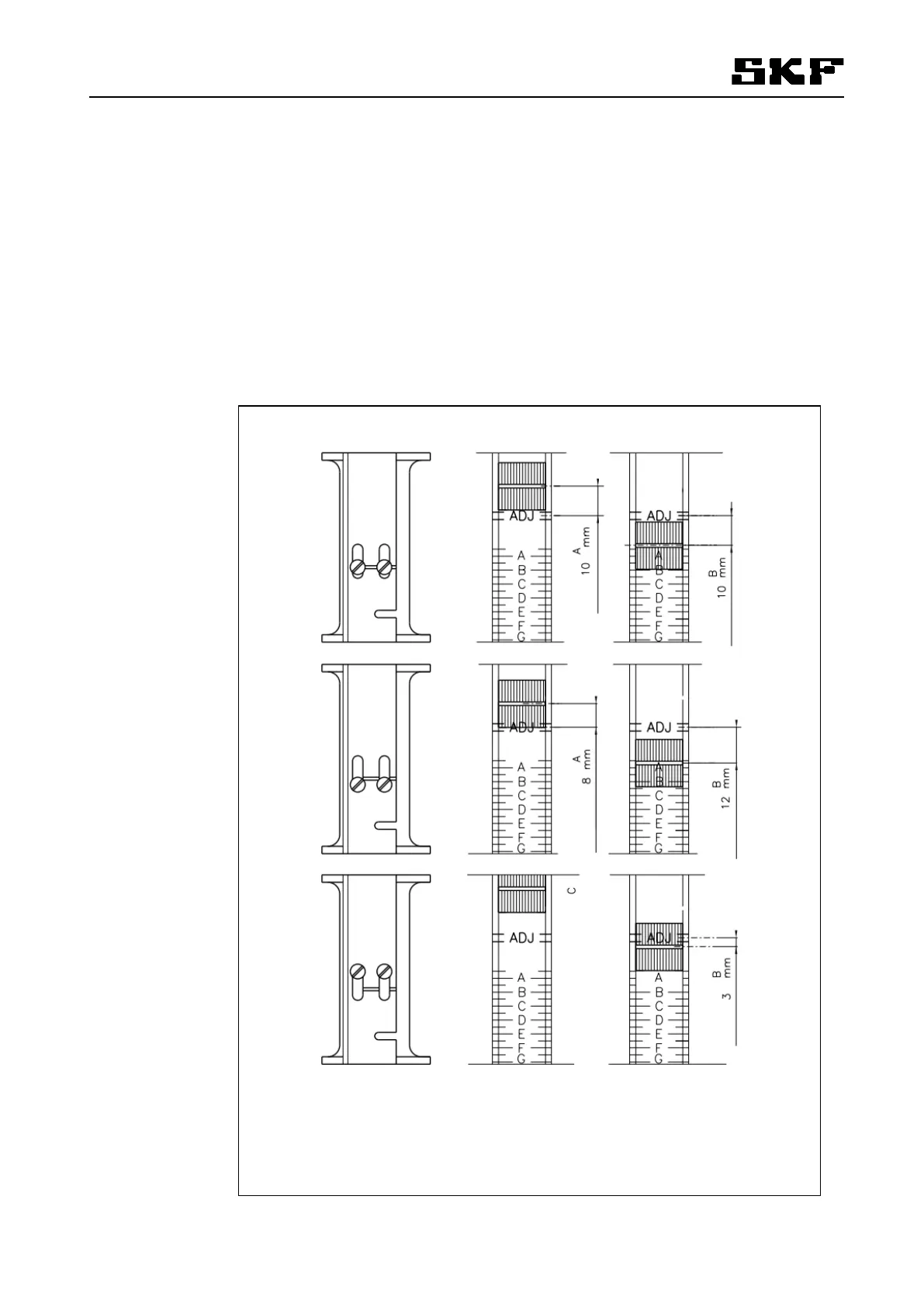
7.6.2 Adjusting the sensors' switching point
The alarm limit for float movement can be adjusted by moving the sensor up or down in its holder. Fig. 24,
Sensitivity adjustment for alarm sensors shows the switching points with three different adjustment set-
tings.
Fig. 24 Sensitivity adjustment for alarm sensors
46125
A High level alarm
B Low level alarm
C No high level alarm
0