60
8.4.1 Connecting the sensors
The sensors are connected to the terminal blocks 21 - 40 on the electronic card. Make sure to check that the
wires of the sensors are connected in the correct direction. The colour codes, brown and blue, are also
marked on the card. Refer to the Terminal Block Table for the connection order.
The connectors of the unused sensor position must be connected with a jumper. A sensor position without a
sensor or jumper connection causes a continuous alarm state.
When connecting the sensor, the jumpers on the connectors must be removed, otherwise the sensor cannot
give an alarm.
E.g. Connect sensor no. 5
Remove the jumper between connectors 29 and 30.
Connect the brown sensor wire to connector 29 and the blue wire to connector 30.
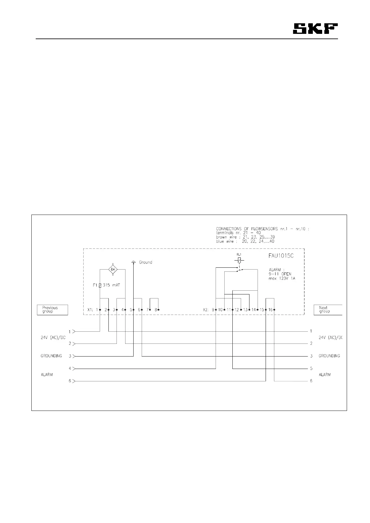
8.4.2 External connections
The connection sequence is shown in the Table Terminal Block Sequence (see section8.7 ) and in Figure
28, External connections, lay-out, which shows how to connect the power supply and alarm output in series
between several measurement groups.
Figure 28. External connections layout
318763