46
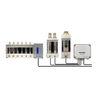
7.3.2 Control unit
The control unit is enclosed in a polycarbonate casing. The electronic card, FAU1015S, is attached to the
cover of the case. The wires of the sensors and the cables of the power supply and alarm outputs are con-
nected to the card’s terminal blocks. The casing cover has a window with an indicator light for each sensor
and a voltage supply indicator light.
Polycarbonate, size 170 x 140 x 95 (W x H x D)
Protection class, IP65
24V AC (17 - 27V AC RMS)
Max. power consumption: 150 A
315 mAT, 5x20mm glass tube fuse
Flow pipe -specific, voltage-free relay contact that opens in the event of an
alarm
Terminal blocks for max. 2.5 mm² wires
1 ... 10 pcs BS-12030 alarms
LEDs
The alarm electronics box is equipped with indicator lights on the cover:
The probe-specific alarm indicator switches on when the probe concerned is in alarm
mode. The light is off at other times.
Settings:
The unconnected sensor position indicator can be deactivated by module bridges.
Failsafe features
An individual alarm relay is in alarm mode when:
2 The corresponding sensor is in an alarm mode.
2 The alarm electronics or sensor are de-energized.
2 The sensor wire is broken.
7.3.3 Alarm sensor
Type BS-12030 for flow tubes SF01A, SF20A and SF30A.
Inductive proximity switch with a two-wire connection.
Cable length 5 m.