47
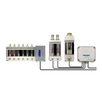
7.4 Operating principle BSS-051015 and BSS-12030
One control unit can be connected to 1 ... 10 BS-0510-C, BS-15-C or BS-12030 alarm sensors.
The monitoring unit monitors the sensor status and, in the event of a sensor alarm, activates a corresponding
alarm signal, which is a relay contact that opens. The alarm mode is switched off when the alarm sensor re-
turns to normal mode.
The sensor circuit is of the failsafe type, i.e. a power failure from the sensor circuit is interpreted as an alarm
state. The alarm output relay is also failsafe-connected. The loss of the relay’s control voltage causes an
alarm state.
The unit has LED indicators for 1... 10 sensors. When the sensor and the relay are in an alarm state, the cor-
responding LED lights up. In addition, a green ON indicator is on to indicate that the module is energized.
7.5 Electrical installation BSS-051015 and BSS12030
The switching and setting points with the electronics module FAU1015S are shown in Figure 22, FAU1015S
lay out.
The terminal block meanings are listed in Table Terminal block sequence (see section 7.8 ).