57
8.2.2 Control unit
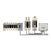
The control unit is enclosed in a polycarbonate casing. The electronics card, FAU1015C, is attached to the
cover of the casing. The sensor wires as well as the power supply and alarm outputs are attached to the
card's terminal blocks. The cover of the casing has a window with an indicator light for each sensor and the
joint alarm status.
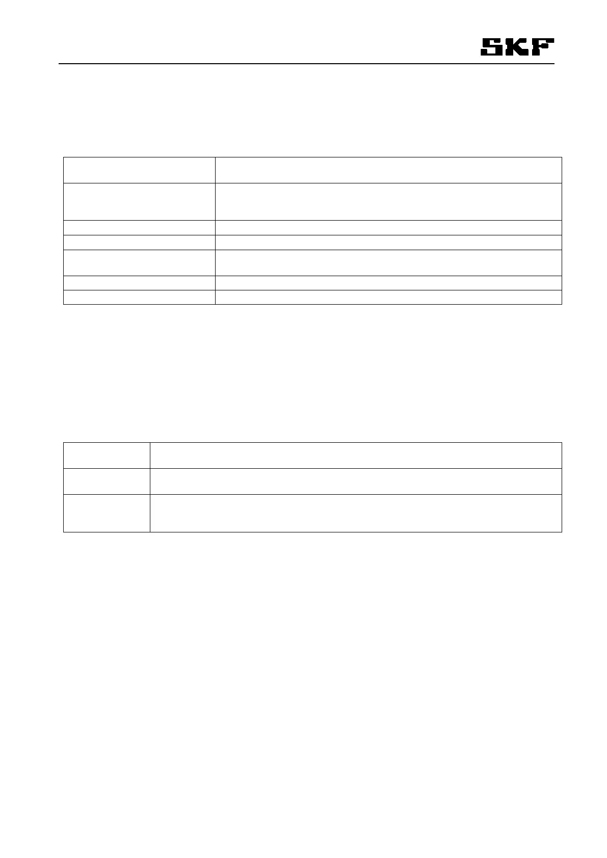
Polycarbonate, size 170 x 140 x 95 (W x H x D)
Protection class, IP65
24V AC (18 - 27V AC RMS)
Power consumption 140 mA max.
400 mA reversible polymer fuse
°
Alarm output, voltage-free relay contact, 1 change-over contact
Max. load 120 VAC/DC, 1A
Terminal blocks for max. 2.5mm² wires
1 ... 10 pcs BS-12030 alarms
Delays
The alarm activation delay can be set to any of the following: 0s, 10s, 50s, 100s.
The alarm exit delay is 1/5 of the activation delay
LEDs
The alarm electronics box is equipped with indicator lights on the cover:
The non-delayed sensor-specific alarm indicator switches on when the sensor in ques-
tion is in alarm mode. The light is off at other times.
Red and green indicator light. Indicates the alarm output status. Green lights up in nor-
mal mode, red in alarm mode.
The electronic card, inside the alarm box, has a green indicator light which:
- flashes every 1s in normal and alarm mode
- flashes 5 times per second during the alarm delay or alarm exit delay.