Section 04 ENGINE
Subsection 07 (AXIAL FAN COOLING SYSTEM)
04-07-2
NOTE:
The following procedures can be done
without removing engine from chassis.
REMOVAL
NOTE:
To facilitate further disassembly, fan nut
may be removed before removing fan housing.
Remove rewind starter, starting pulley, trigger coil
wire from 4-connector housing then fan housing
ass’y.
CLEANING
Clean all metal components in a non-ferrous met-
al cleaner.
DISASSEMBLY AND ASSEMBLY
Remove fan protector.
To remove or install fan pulley retaining nut
no. 17
, lock fan pulley with special holder wrench
(P/N 420 8763 57). At assembly, torque nut to
65 N•m (48 lbf•ft).
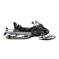
TYPICAL
Fan belt deflection must be as specified when ap-
plying the proper force midway between pulleys.
1. Deflection
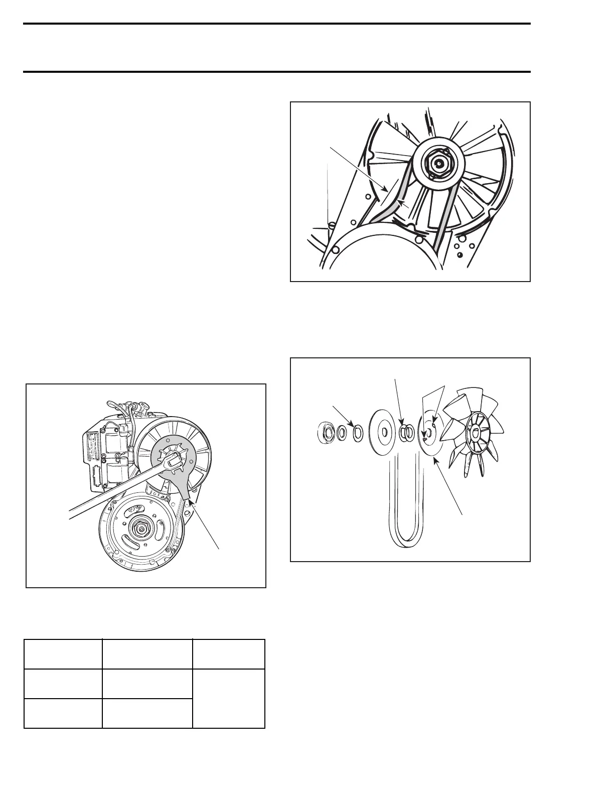
To adjust tension, add or remove shim(s)
no. 15
between pulley halves
nos. 14
and
16
. Install ex-
cess shim(s) between distance sleeve
no. 13
and
half pulley
no. 14
(housing side).
1. Unused shim(s) here
2. Adjust here
3. Positioning noses
4. Some engines only
Some engines have a separate metal pulley half
instead of using back of fan as pulley half. On first
mentioned engines, select pulley halves so that
the one with 2 positioning noses will be on fan
side. Ensure to insert these noses into fan notches.
ENGINE
TYPE
BELT
DEFLECTION
FORCE
APPLIED
443
8.5 mm
(11/32 in)
5 kg
(11 lb)
503
9.5 mm
(3/8 in)
A09C08A
420 8763 57
A09C0JA
1
1
2
3
4
A09C0VA