Section 05 TRANSMISSION
Subsection 03 (DRIVE PULLEY)
05-03-5
24,25, O-ring and Slider Shoe
Check if O-rings are cracked, cut or crushed. Re-
place as required.
Check slider shoes for wear. Replace if groove is
not apparent on top.
5,29, Fixed Half and Governor Cup
Inspect splines and free play between both parts.
Maximum free play is 0.5 mm (.020 in) measured
at calibration screw radius. Replace if required.
7,20, Sliding Half and Spring Cover
Bushing
Visually inspect coating. Replace if worn.
Sliding Half Bushing Replacement
These bushings can be replaced using tools
which are not available at time of printing.
Spring Cover Bushing Replacement
Under normal use there is no need to replace this
bushing.
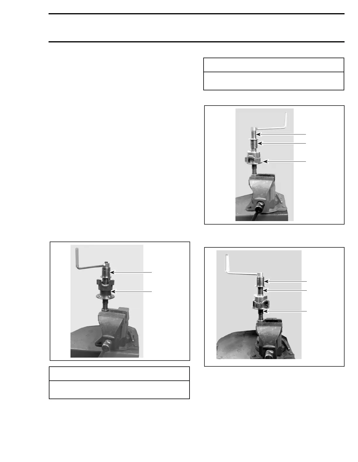
Use tools (P/N 529 0313 00 and 529 0312 00) to
remove old bushing.
Apply retaining compound Loctite 648 outside of
bushing then press it down to counterbore from
outside end. Use spring compressor (P/N 529
0151 00) and appropriate tools.
Start driving bushing into spring cover.
1. Note upper tool side
Press bushing.
1. Note upper tool side
ASSEMBLY
NOTE:
This drive pulley is lubrication free.
Do not
lubricate
any component.
-
CAUTION
Bushing must be bonded with retaining
compound.
A01D2MA
529 0313 00
529 0312 00
-
CAUTION
Insert bushing from outside (governor side)
of spring cover.
A01D2NA
529 0313 00
529 0312 00
1
A01D2OA
529 0313 00
529 0312 00
1