Section 06 ELECTRICAL
Subsection 06 (TESTING PROCEDURE)
06-06-11
TYPICAL
If readings do not correspond to the above men-
tioned indications, replace switch.
If readings are acceptable, check other switches.
If none of these verifications are conclusive, the
problem finds its source in the main wiring har-
ness. Proceed as follows:
NOTE:
For this next step, no stop switch must be
connected to the main wiring harness.
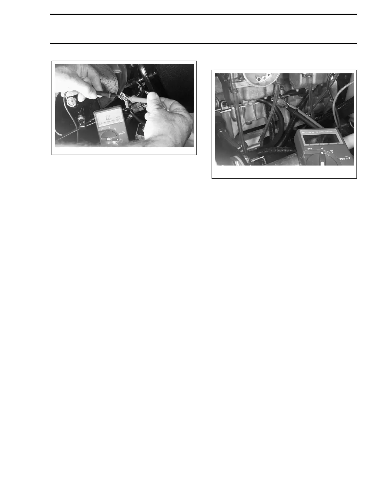
Disconnect all stop switches from the main wiring
harness and check the continuity of each wire by
connecting probes to the end of wires of the
same color. Repeat with all other wires. It is im-
portant to mention that all wires of the same color
within a given harness are connected together.
These wires should therefore have a closed cir-
cuit. On the other hand, BLACK and BLACK/YEL-
LOW wires must have an open circuit (0.L
M
Ω
).
Repair or replace if necessary.
4. IGNITION GENERATOR COIL
VOLTAGE TESTING
General
When manually starting the engine while the
spark plug is installed, the engine will tend to ac-
celerate beyond the compression point. This will
result in higher magneto output power.
1. Disconnect the 4-wire housing between the ig-
nition module and the magneto wiring harness
(4-20).
2. Connect multimeter probes to GREEN and
WHITE wires (female end), then bring selector
to and scale to 00.0
VAC
.
3. Activate the manual starter and check values in-
dicated by the multimeter.
4. Repeat operation 3 times.
5. Compare readings with those appearing in the
IGNITION table.
5. TRIGGER COIL VOLTAGE
TESTING
1. Disconnect 4-wire housing between the igni-
tion module and the engine (4-20).
2. Connect multimeter probes to RED/WHITE
wire (female side) and to the engine, then bring
selector switch to and scale to 00.0
VAC
.
3. Activate the manual starter and check values in-
dicated by the multimeter.
4. Repeat operation 3 times.
5. Compare readings with those appearing in the
IGNITION table.
6. HIGH VOLTAGE COIL VOLTAGE
TESTING
1. Disconnect spark plug cap from right spark plug
(magneto side).
2. Fasten alligator clip to spark plug cable, near
the spark plug.
3. Connect other multimeter wire to high voltage
coil screw, then place selector switch to and
scale to 0.00
VAC
.
4. Activate the manual starter and check values in-
dicated by the multimeter.
5. Repeat operation 3 times.
A05E09A
V
˜
A03E1JA
V
˜
V
˜