Section 04 ENGINE
Subsection 02 (443 AND 503 ENGINE TYPES)
04-02-8
– Mount piston over connecting rod with the let-
ters
AUS
(over an arrow on the piston dome)
facing in the direction of exhaust port.
1. Exhaust
– Install piston pin puller (P/N 529 0210 00) and
turn handle until piston pin is correctly posi-
tioned in piston.
– Remove piston pin puller and expansion sleeve.
– Install circlips as described below.
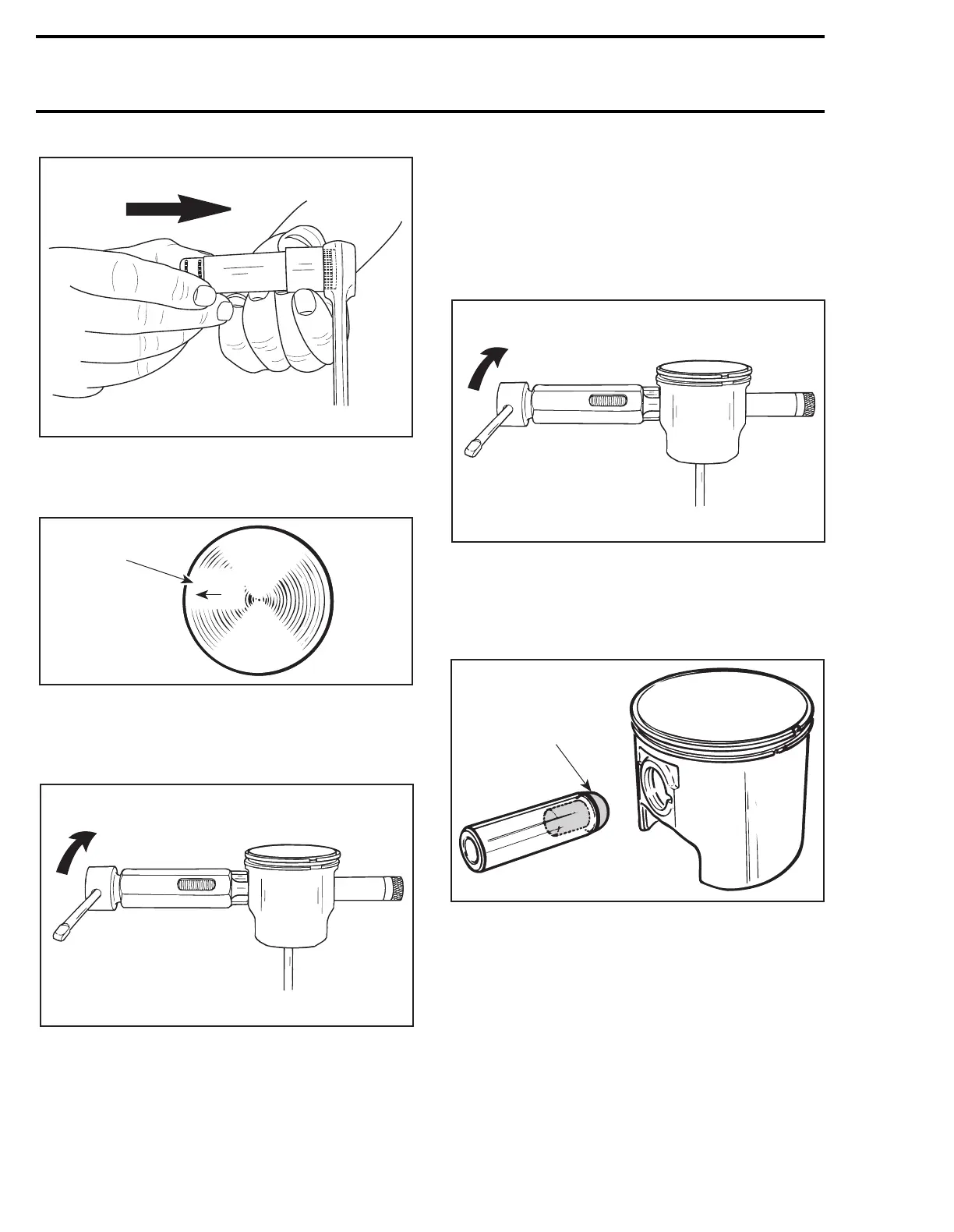
– When installing new needle bearing, insert nee-
dles with thrust washers. Instead of expansion
sleeve, needles are held in place by 2 inner
plastic cage halves.
– Use piston pin puller (P/N 529 0210 00) to insert
piston pin. Plastic halves should come off pis-
ton. If not, pull them out using long nose pliers.
– Install circlips as described below.
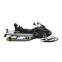
503 Engine
To center the piston pin with the connecting rod
bearing, use centering tool (P/N 529 0091 00).
NOTE:
The circlip on the opposite side can be in-
stalled before pin installation, the tool will easily
come out.
All Engines
To minimize the effect of acceleration forces on
circlip, install each circlip so the circlip break is at
6 o’clock as illustrated. Use piston circlip installer
(P/N 529 0086 00).
A21C02A
A01C01A
AUS
1
A21C01A
A21C01A
A01B1SA
529 0091 00