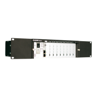
The Slican IPM-032 is a telecommunication server designed for small and medium-sized companies, available in both wall-mounted (WM) and 19" rack (2U) versions. It offers a modular and scalable construction, allowing for flexible expansion and adaptation to various business needs.
Function Description
The IPM-032 provides comprehensive telecommunication services, including VoIP functionality as a standard feature. It supports intelligent routing of outgoing calls (LCR) to optimize costs, enhance reliability, and facilitate networking. The server allows for real-time monitoring of operating parameters through its managing application, and it is compatible with dedicated digital system and VoIP Slican phones. Users can configure system phones directly from the server's management application.
Cost management is a key feature, with internal server mechanisms and an additional application, BillingMAN, for managing call costs and tariffs. The system supports 99 voice announcements for various purposes, such as DISA/infolines or DND messages, and provides subscriber services confirmed with voice messages. It also integrates with PC applications for enhanced functionality.
The server offers a variety of interfaces and terminal support:
- Analogue Ports: Supports extension phones with pulse dialling and DTMF, offering full functionality for DTMF phones and internal CLIP signalling with public signal transfer.
- ISDN Ports: Configurable BRA 2B+D terminals (internal/external) supporting DSS1 protocol (EURO – ISDN), MSN, and DDI. It also supports ISDN 30B+D with DSS1 protocol (EURO – ISDN) and DDI.
- Public Analogue Lines (POTS): Complies with ASS signalling.
- GSM: Tri-Band 900/1800/1900MHz support.
- VoIP: Adheres to SIP (v.2.0), IAX (v.2.0), and SSL (Slican Smart Link) protocols.
- Up0 Terminals: For digital system phones.
- Interfaces: Includes LAN/WAN (Ethernet 10/100 Mbps) and USB 2.0.
The IPM-032 also supports Slican doorphones and the Slican DPH access control system.
Important Technical Specifications
- Power Supply: Operates on an alternating current network of ~230V, 50Hz.
- Maximum Power Consumption: 65W.
- Overvoltage Protection: Cards are protected against overvoltage in the telecommunications network.
- Battery Support: Supports 3 x 12V/7Ah batteries (recommended EP 7-12 batteries, EUROPOWER or their equivalents) for a server capacity of approximately 20 ports using 7Ah accumulators.
- Dimensions:
- 2U Version (IPM-032.A8x4.2U / IPM-032.L8x4.2U): 2U (height 91 mm, depth 310 mm).
- WM Version (IPM-032.A6x4.WM / IPM-032.L6x4.WM): Width 252 mm, height 276 mm, depth 120 mm.
- Connectors:
- VoIP: SIP, IAX, SSL, CTS IP phones.
- GSM: Tri-Band 900/1800/1900MHz.
- S0 (2B+D) configurable: DSS1 protocol (EURO-ISDN).
- S2M (30 B+D): DSS1 protocol (EURO-ISDN) External.
- Up0 for CTS-102/CTS-202/CTS-330: Terminals for system phones with a signalling system developed by Slican.
- Analogue: According to ASS signalling.
- Data Storage: Supports SD memory cards up to 8 GB.
- Channels: Up to 32 channels available depending on the number of licences purchased.
Usage Features
- Remote Management: The server can be managed remotely via a PC using LAN, Internet, or an optional modem.
- Modular Design: Its modular construction allows for easy expansion and customization by adding various port modules and submodules.
- Card Installation: Cards are installed in dedicated slots. For 2U versions, slots 1 to 8 are available for expansion cards, with slots 3 and 4 specifically supporting IPL1E1 or IPL32VoIP cards. For WM versions, slots 1 to 6 are available, with slots 3 and 4 supporting IPL1E1 or IPL32VoIP cards.
- Power Supply Unit (PSU): Dedicated slots for the power supply unit (PS slot) and controller (PU slot).
- Battery Management: The SM.3BATC submodule manages charging and supplying current from batteries for server operation.
- Firmware Updates: The server supports quick recovery to previous versions of firmware.
- SD Card for Storage: An SD card can be used for storing voice announcements and other data, with 32 channels available when using an SD card.
Maintenance Features
- Easy Access: The design allows for easy access to internal components for installation and servicing.
- LED Indicators: The front panel features LEDs (POWER, STATUS, LINES, PHONES, LED1-LED4, LAN, WAN) that provide visual feedback on the server's operational status and network activity.
- POWER LED: Lit when the server is active, blinks during power from accumulators, and is off when the server is turned off.
- STATUS LED: Blinks fast during system initialization, blinks slowly for non-critical errors, stays lit for normal operation, and is not lit for proper operation.
- LINES LED: Indicates public line status (blinks fast for line damage, stays lit for busy, not lit for free).
- PHONES LED: Indicates internal line status (blinks fast for line damage, stays lit for ringing/busy, not lit for free).
- LAN/WAN LEDs: Yellow indicates the first layer of transmission is present, green blinks if a transmission is in progress.
- Reset Functionality: The HRESET pins allow for turning off the server and resetting it after activation.
- Battery Replacement: Batteries should be replaced in case of explosion or incorrect type. Used batteries must be disposed of according to regulations.
- Environmental Requirements:
- Temperature: Ambient temperature at server operation area: +10°C to +25°C (recommended air-conditioned room 22°C).
- Humidity: 40-70%.
- Noise: Due to emission of noise (fans in the power supply unit), it is not recommended to mount the server in office rooms, close to where people work.
- Location: The server must not be located in rooms with high dust concentrations or rooms with high-intensity electromagnetic fields.
- Interference: The device may begin to malfunction, be affected by interference, or discolour if installed in places exposed to direct sunlight, strong vibrations or mechanical impacts, or live antenna radiation (short wave in particular).
- Electrical Requirements: The device must have a correct system of setting to zero in the power network or must be grounded. Conduct periodic checks of the protective ground/earth. All devices connected to the server must have the certificates of conformity meeting the current standards for the European Union.
- Safety Precautions:
- The server should be installed in rooms with strong sunlight, high humidity, or high dust concentration.
- Avoid locations with strong electromagnetic fields.
- The 2U server should be mounted in a factory 19" casing or any other casing owned by the user that meets safety requirements.
- The server is installed in the user's cabinet, making sure there is enough room for each server component system.
- The servers should be supplied from a 230 V, 50 Hz AC power network.
- A 230 V power network socket used for the server should have a protective screw and the efficiency of its anti-shock protection should be confirmed by an appropriate protocol. Non-compliance with this requirement constitutes a risk of electric shock.
- Access shall be provided to the main grounding bar (terminal) in the installation area so that it is possible to ground/earth the server (by connecting a cable with a cross-section conforming to an appropriate standard, to the protective grounding terminal marked ⏚).
- Always ground/earth the server (regardless of the fact whether it is mounted in a factory casing or the user's cabinet) with regard to its impact on the efficiency of protection against over voltage from telecommunication lines connected to the server. Due to that, remember to tighten sufficiently the mounting screws of the front panels of port cards to the shelf housing.
- A battery connection consists in making a connection between the BATTERY socket in the master power supply and the socket on the battery casing (connecting cable is supplied with the casing).
- Making compensating connections is optional and depends on the type of cabinet in which the system is mounted. If the rack manufacturer specifies that the buses to which shelves with ports are screwed ensure an electrical connection between individual shelves and the external casing or frame, it is not necessary to make such connections. Otherwise, compensating connections must be added (cross section of the cable should be selected according to effective standard) between individual shelves and the rack protective terminal and marked ⏚ (the same symbol is used for marking locations on the server shelf casings where the compensating cable should be connected).