Slican IPM-032
4.2 Controller cards
4.2.1 Controller card IPM1APU
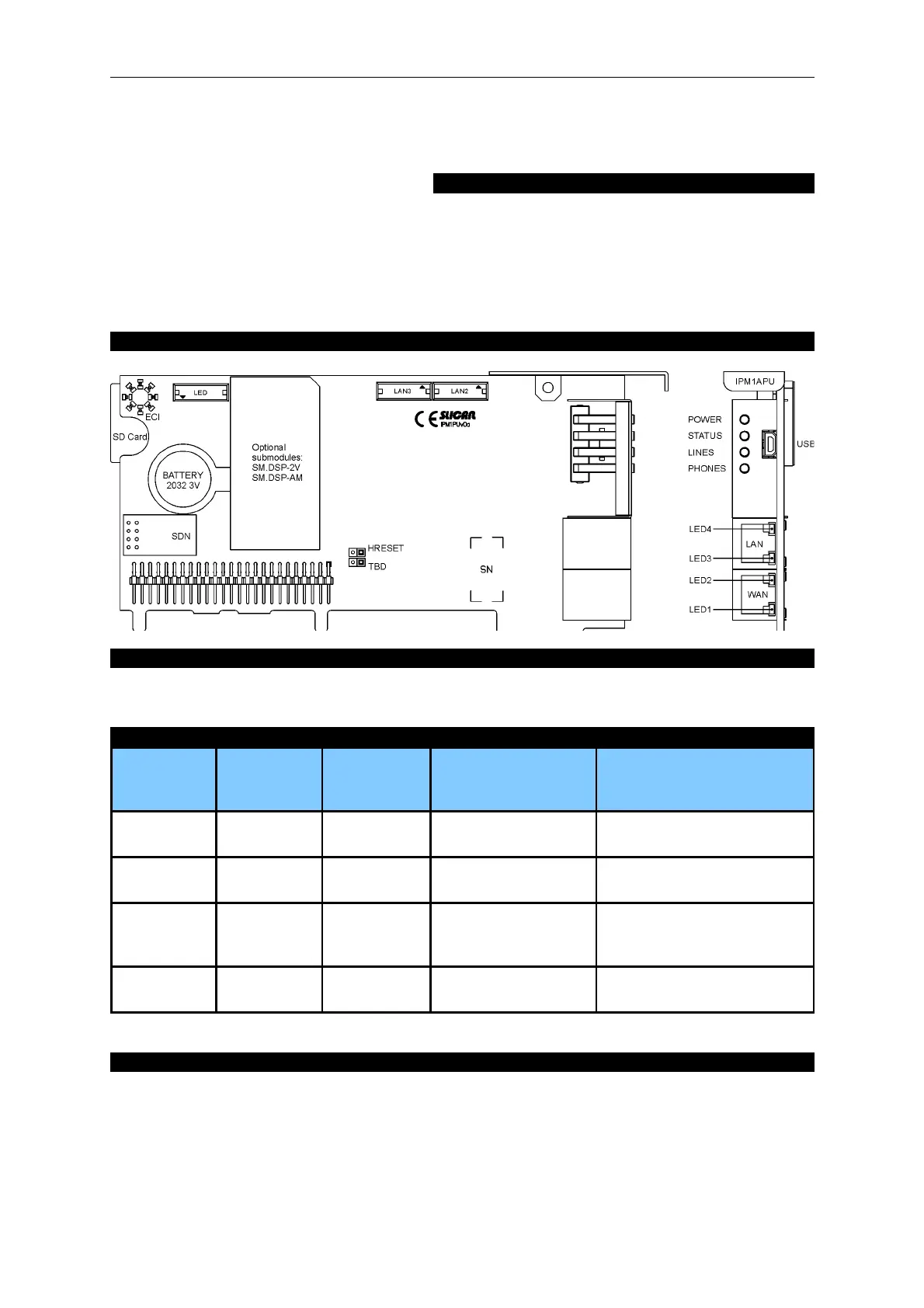
Print name: IPM1PUv0a Short description of the card:
The controller card is the main server port. It is
responsible for managing processes in the system.
It also supports the VoIP (g.711a) function and
EbdRec.
Card marking: IPM1APU
View of the card and its front panel:
Installing the card in the server:
The controller card is placed in the base board slot marked Slot PU. This module is used for installing
SDN sub modules, optionally: DSP-2V(codecs G.729 and G.711u), DSP-AM (analogue modem), SD
card
Description of LEDs on the front panel (applies to all types of controller):
Behaviour
of LEDs
POWER
power supply
status
STATUS
server status
LINES
public line status
PHONES
internal line status
blinks fast System
initialisation
Critical error Public line damaged Internal line damaged
blinks
slowly
- Non-critical
error
Call on at least one
line
At least one phone is ringing
(a call)
stays lit Normal
operation
- At least one line is
busy
At least one internal line is
busy (call or number
selection)
is not lit - Proper
operation
All lines are free All internal lines are free
Description of outputs on the front panel:
USB – a Mini-USB port for communication with a computer (e.g. ConfigMAN)
WAN – RJ-45 port for internal router (MAC address on the label)
LAN – RJ-45 port for internal router (MAC address on the label)
Meaning of LEDs on RJ45 ports:
• Yellow: stays lit if the first layer of transmission is present.
• Green: blinks if a transmission is in progress.
Issue 1.01 21