Technical documentation
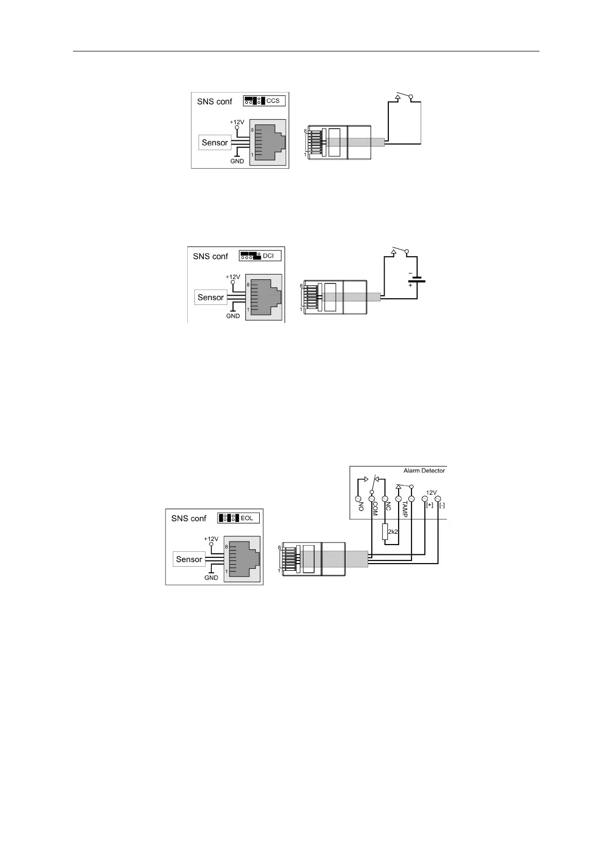
• CCS – triggered by a short-circuit
The sensor is triggered after the loop is closed. Maximum resistance of the loop is 1 kΩ.
The voltage between pins 3 and 6 is 12 V DC with a max. charge of 200 mA.
The sensor reaction time is 100 ms.
• DCI – triggered by voltage
The sensor will be triggered after supplying voltage from the range 5~30 V DC to pins 4 and 5. Max
current consumption by the sensor is 5 mA.
The voltage between pins 3 and 6 is 12 V DC with a max. charge of 200 mA.
The sensor reaction time is 100 ms.
NOTE:
The polarity of the supplied voltage is important. Safety resistors are activated if the polarity is
changed.
• EOL – Parameter loop – triggered by a resistance of 2200 Ω
The sensor is active when loop resistance is in the range from 2000 Ω to 2500 Ω. A short circuit or
break in the loop sets the sensor to an inactive state.
The voltage between pins 3 and 6 is 12 V DC with a max. charge of 200 mA.
The required relay operation mode is selected by putting jumpers marked SNS2 and SNS4 in the
correct positions.
34