HGMS62 Split Type Genset Controller User Manual Page 22 of 58
Mains R phase monitoring outputs after passing the
fuse.
Mains R Phase Voltage
Monitoring Input
Connect mains R phase, 10A fuse is used for
controller.
Mains S Phase Voltage
Monitoring Input
Connect mains S phase, 10A fuse is used for
controller.
Mains T Phase Voltage
Monitoring Input
Connect mains T phase, 10A fuse is used for
controller.
Genset U phase monitoring outputs after passing the
fuse.
Genset U Phase Voltage
Monitoring Input
Connect U phase of genset output, 10A fuse is used
for controller.
Genset V Phase Voltage
Monitoring Input
Connect V phase of genset output, 10A fuse is used
for controller.
Genset W Phase Voltage
Monitoring Input
Connect W phase of genset output, 10A fuse is used
for controller.
Connect N line of genset output.
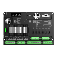
Connector A (Connect to HGMS62D)
Connect terminal 6 (B+ OUT) to this terminal through
a power switch to supply for positive of HGMS62M.
Supply power to positive of HGMS62D.
Negative of controller power.
RS232 communication port is connected with
HGMS62D.
Shielding line is required, shielded layer is connected
to terminal 7 GND.
Main terminal 2 (DC B+) is connected to this terminal
after passing the fuse.
The internal part is connected with negative of
controller.
Emergency input connect to external emergency
stop button.
Connector B (Connect to ESC)
B+ is supplied by 2 points, rated 10A.
Connect to positive of ESC power.
The controller inside is connected to speed sensor of
Main terminal 26. Connect to speed sampling
terminal of ESC.
The controller inside has connected to B-.
The controller inside has connected to B-.