- 10 -
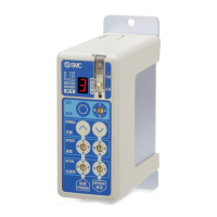
(4) Power ON alarm (error)
Ensure the stop is not activated and then supply 24VDC power.
LED color Status Function
Green Normal POWER
Red Error ALARM
If the LED [PWR] lights in green, the controller is in the normal condition.
However, if the LED [ALM] lights in red, the controller is in the alarm (error) condition.
Caution
In case of alarm (error) condition:
Connect a PC or the teaching box to the CN4 serial I/O connector and check the details of the alarm
Then, remove the cause of the error referring to the
“12. Alarm Detection (page 48).”
* Please refer to the manuals of the controller setting software or the teaching box for details of the
alarms.
(5) Operation pattern setting
Setup the op
eration pattern (step data, basic parameter and return to origin parameters) to specify
the target position, speed, etc. by using a PC (with the controller setting software) or the teaching
box.
Please refer to the manuals of the controller setting software or the teaching box for how to setup the
operation pattern.
(6) Trial run (actuator adjustment)
Please refer
to the manuals of the controller setting software or the teaching box manual for how to
perform a trial run.
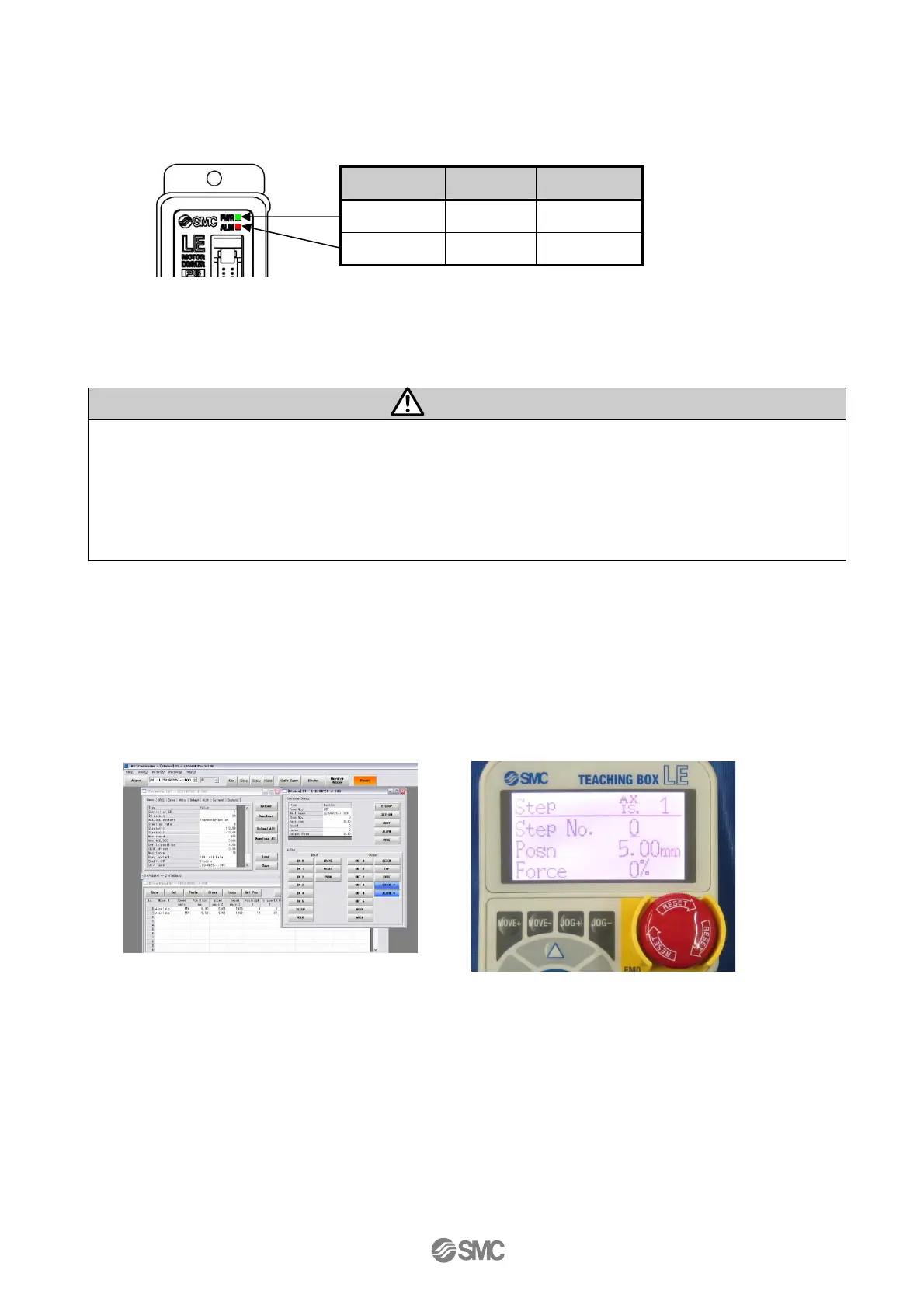
PC (Normal mode)
Teaching box
Controller
 Loading...