- 12 -
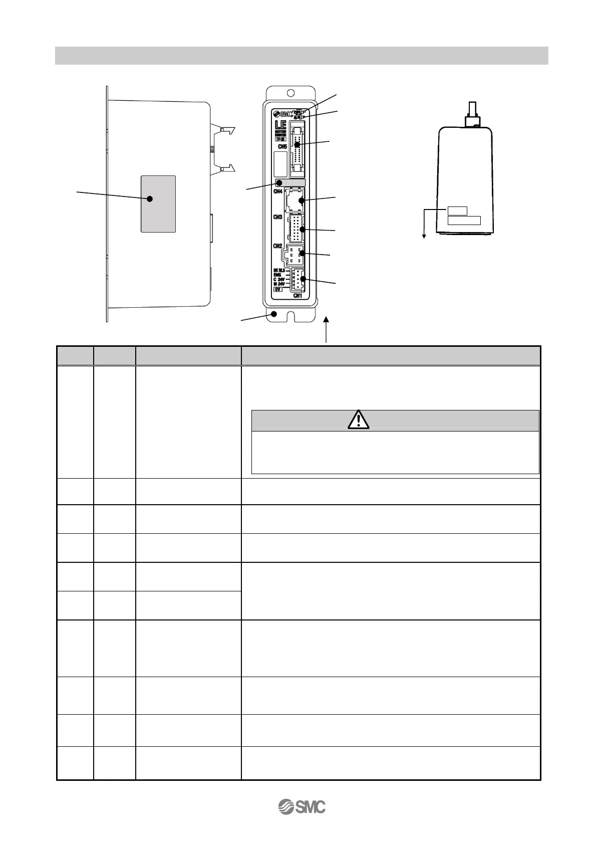
3.2 Parts description
The detailed descriptions of each part are as follows:
No. Label Name Description
1 PWR Power LED (green)
Power ON/No alarm: Green light
Data (step data, parameter) writing /green light flashing
caution
Do not turn off the controller input power or remove the
cable while data is being written (green light flashing).
*Data (step data ,parameter) may not be written correctly.
2 ALM Power LED (red) Power ON/Alarm: Red light
3 CN5
Parallel I/O
Connector (26 pins)
Used to connect PLC, etc. with the I/O cable.
(11 inputs and COM, 13 outputs and COM)
4 CN4
Serial I/O
Connector (8 pins)
Used to connect the teaching box, PC, etc.
5 CN3
Encoder connector
(16 pins)
6 CN2
Motor power
connector (6 pins)
Used to connect the actuator cable.
7 CN1
Power connector
(5 pins)
Used to connect the controller power supply (24VDC) with the
power supply plug.
Common power(-),Motor power (+),Control power(+),Stop
signal(+),Lock release(+)
8 -
Compatible actuator
label
The label indicating the applicable actuator model.
It also indicates the type of the parallel I/O (PNP/NPN).
9
-
Controller label The label indicating the part number of the controller.
10
-
FG Functional ground
Side (controller version)
SV1.00
ARX8300073
Label of controller version
(Example) controller version
“SV1.00”
(9)
(8)
(1)
(2)
(3)
(5)
(4)
(6)
(7)
(10)
Side
 Loading...