- 16 -
4. External Wiring Diagram
The typical connections for each connector of this controller (CN1 to CN5) are as shown below.
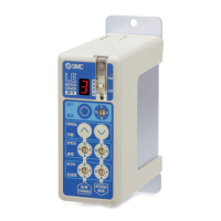
4.1 CN1: Power connector
* Please refer to “5. CN1: Power supply plug (page 18)” for how to wire the CN1 connector.
Caution
The controller power supply (24VDC) do not use the power supply of “rush-current restraining type”.
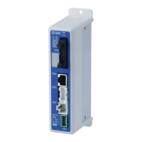
4.2 CN2: Motor power connector and CN3: Encoder connector
Connect the controller and the actuator with the actuator cable (LE-CP--).
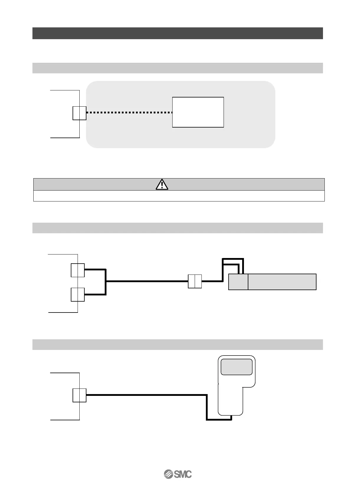
4.3 CN4: Serial I/O connector
(1) Connection with the teaching box
Controller
Actuator cable
CN2
CN3
Actuator
Motor
Controller
CN4
Teaching box
(The 3m cable is provided.)
Controller
CN1
Controller power
supply 24VDC
(The 24VDC power supply and the power cable should be obtained separately.)
Power cable
 Loading...