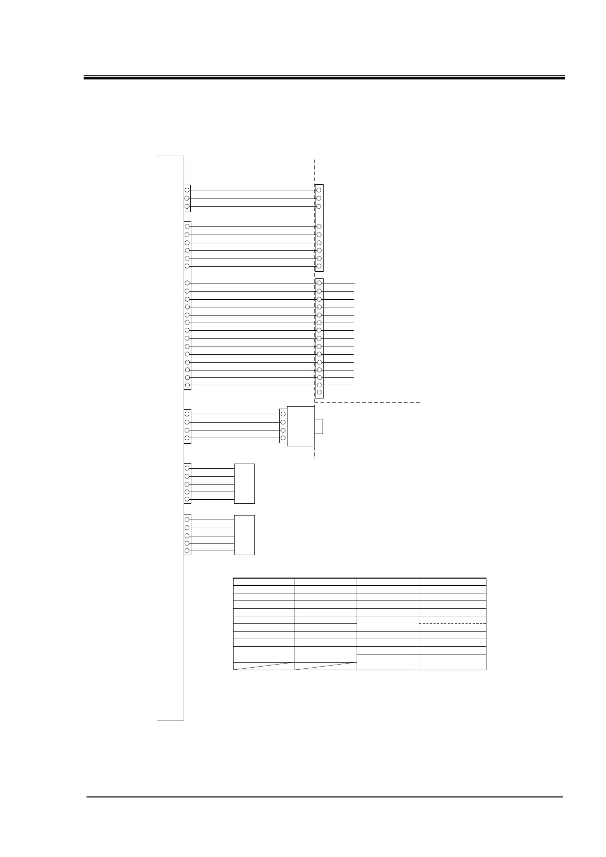
Fig. 8-5 Electrical schematic diagram (2/2)
Blue
Yellow
/Green
(CN3)
1
2
3
4
5
【EV2】
White
Yellow
Orange
Blue
Red
「For heating」
(CN2)
1
2
3
4
White
White
Customer power connection port
1-phase HRR***-**-20:200-230VAC 50/60Hz
L N
【AC_CN】
(CN2)
1 3
Black
Black
【CB】
「Circuit breaker」
Black
Black
[G1]Yellow/Green
[G4]
Yellow/Green
「Pump」
「Option T」
「High pressure pump」
White
「Option T: Black」
(CN3) 1
2
(CN5)
Black
Black
(CN1)
[G2]Yellow/Green
1
3
【PCB3】
Blue
Brown
Brown
Blue
Blue
Blue
Brown
Blue
Blue
Blue
Blue
Blue
Blue
(CN1)
(CN8)
1
2
4
5
2
1
13
14
15
16
3
4
7
9
10
11
12
Red
【PT1】
「Circulating fluid outlet」
(CN1) 1/2
1A
2A
3A
「Circulating fluid return 」 【T1】
(CN5)
「Refrigerator suction」 【T2】
3
4
Black
「Ambient temperature」 【T3】
5
6
「Refrigerant high pressure」
10
14
16
「Refrigerant low pressure」
17
21
23
「DI sensor」
「Option D」
Brown
Blue
Blue
18
Brown
(CN6) 1/2
Blue
「Option T」
【C3】
【PM】
【DCPS】
1
3
5
【PCB2】
(CN2)
1 3
[G3] Yellow/Green
[R]
[S]
[C]
【TH】
Black
Black
Black
2
4
【C2】
【CM】
(CN1)
31 2 4 6 7 5
[G5]
Yellow/Green
【C1】
Black
Black
Black
1 3
7 8 9 6
Black
Yellow
/Green
Brown
Blue
「In the device」
「Outside the
device」
For air-cooled type「Other than option U」
【FAN】
(CN4)
【PC B1】
Black
Black
1
2
Brown
Blue
1
2
Black
Black
1
2
Brown
Blue
Black
【PS1】
「Circulating fluid outlet」
Brown
Blue
Blue
1
2
3
9
13
15
【PS2】
Brown
Blue
Blue
1
2
3
【PS3】
Brown
Blue
Blue
1
2
3
20
22
24
【DI】
Brown
Blue
Blue
1
2
3
Brown
Blue
Brown
Blue
8
5
6
7
4
1
2
5
Red
Red
Red
Red
【LS1】
【LS2】
Brown
Blue 16
15
2
1
Red
Black
【SVDI】
「DI solenoid valve」
「Water leakage detector 」
23
24
22
【WLS】
Red
Black
White
1
2
3
「Flow rate sensor」
35
36
34
【FL】
Brown
Blue
Black
[G5]
Yellow/Green
Black
Black
1 3
7 9 6
Black
Yellow
Blue
For air-cooled type「Option U」
【FAN】
(CN4)
「In the device」
「Outside
the device」
White
Red
Blue
4312
25
26
(CN1) 2/2
Blue
Blue
Blue
Blue
Blue
Brown
Blue
Blue
Blue
(CN7)
Brown
Blue
Brown
Blue
Brown
Blue
Blue
Blue
Blue
Blue
Blue
Blue
Blue
Blue
1B
2B
3B
7
8
9
10
12
11
15
16
17
18
19
20
21
22
23
24
25
26
27
28
4
7
8
5
6
1
9
2
3
1
9
2
10
3
11
4
12
5
13
6
14
7
15
8
(CN6) 2/2
【PCB4】
「Outside the device」 *Front panel
37
38
39
1
2
4
40
5
(CN2)
(CN1)
「Maintenance communication (USB)」
5
【EV1】
Orange
Red
Yellow
Blue
Green
「For cooling」
「Contact input/output」
「Serial communication」
「External temperature sensor」
【PT2】
「Outside the device」 *Rear panel
External communication section for customer connection
1. 【 】: Circuit symbol
2. ( ) : Connector number
3. 「 」 : Reference information
Black
「In the device」
Brown
Blue
Blue
Circuit symbol
【AC_CN】
Description Circuit symbol Description
【LS1,2】
【T1~3】
【PT1,2】
【EV1,2】
【PS1~3】
【DCPS】
【CB】
Power socket
Tank level switch
Thermistor sensor
Temperature sensor
Electronic expansion valve
Pressure sensor
DC24Vpower supply
Circuit breaker
【PCB1】
【PCB4】
【PCB3】
【PCB2】
【PM】
【CM】
【FAN】
【C2】
Solenoid valve for DI
"Option D"
【SVDI】
【C3】
Main board
USB boar
Display boar
AC power board
Fan motor
Compressor
Operating capacitor for CM
Operating capacitor for PM
"Option T"
Pump
High pressure pump "Option T"

 Loading...