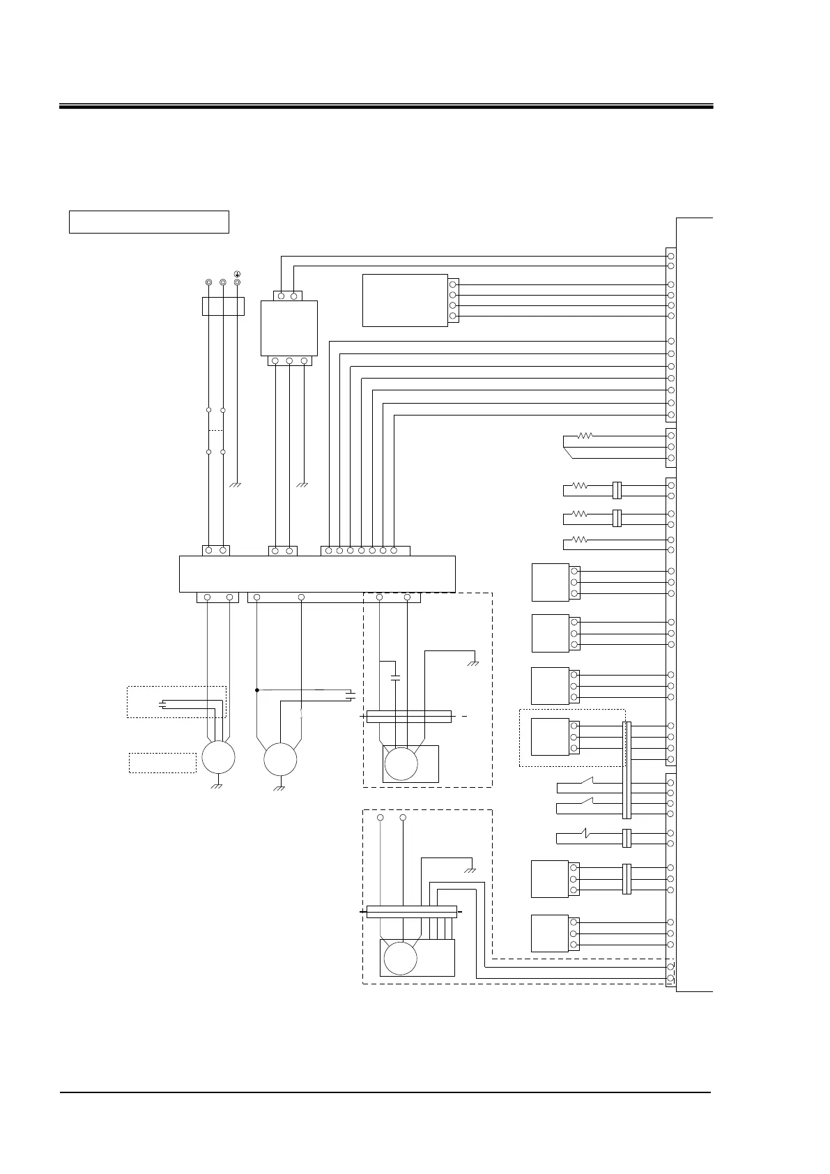
Fig. 8-5 Electrical schematic diagram (1/2)
Blue
Yellow
/Green
(CN3)
1
2
3
4
5
【EV2】
White
Yellow
Orange
Blue
Red
「For heating」
(CN2)
1
2
3
4
White
White
Customer power connection port
1-phase HRR***-**-20:200-230VAC 50/60Hz
L N
【AC_CN】
(CN2)
1 3
Black
Black
【CB】
「Circuit breaker」
Black
Black
[G1]Yellow/Green
[G4]
Yellow/Green
「Pump」
「Option T」
「High pressure pump」
White
「Option T: Black」
(CN3) 1
2
(CN5)
Black
Black
(CN1)
[G2]Yellow/Green
1
3
【PCB3】
Blue
Brown
Brown
Blue
Blue
Blue
Brown
Blue
Blue
Blue
Blue
Blue
Blue
(CN1)
(CN8)
1
2
4
5
2
1
13
14
15
16
3
4
7
9
10
11
12
Red
【PT1】
「Circulating fluid outlet」
(CN1) 1/2
1A
2A
3A
「Circulating fluid return 」 【T1】
(CN5)
「Refrigerator suction」 【T2】
3
4
Black
「Ambient temperature」 【T3】
5
6
「Refrigerant high pressure」
10
14
16
「Refrigerant low pressure」
17
21
23
「DI sensor」
「Option D」
Brown
Blue
Blue
18
Brown
(CN6) 1/2
Blue
「Option T」
【C3】
【PM】
【DCPS】
1
3
5
【PCB2】
(CN2)
1 3
[G3] Yellow/Green
[R]
[S]
[C]
【TH】
Black
Black
Black
2
4
【C2】
【CM】
(CN1)
31 2 4 6 7 5
[G5]
Yellow/Green
【C1】
Black
Black
Black
1 3
7 8 9 6
Black
Yellow
/Green
Brown
Blue
「In the device」
「Outside the
device」
For air-cooled type「Other than option U」
【FAN】
(CN4)
【PCB1】
Black
Black
1
2
Brown
Blue
1
2
Black
Black
1
2
Brown
Blue
Black
【PS1】
「Circulating fluid outlet」
Brown
Blue
Blue
1
2
3
9
13
15
【PS2】
Brown
Blue
Blue
1
2
3
【PS3】
Brown
Blue
Blue
1
2
3
20
22
24
【DI】
Brown
Blue
Blue
1
2
3
Brown
Blue
Brown
Blue
8
5
6
7
4
1
2
5
Red
Red
Red
Red
【LS1】
【LS2】
Brown
Blue 16
15
2
1
Red
Black
【SVDI】
「DI solenoid valve」
「Water leakage detector 」
23
24
22
【WLS】
Red
Black
White
1
2
3
「Flow rate sensor」
35
36
34
【FL】
Brown
Blue
Black
[G5]
Yellow/Green
Black
Black
1 3
7 9 6
Black
Yellow
Blue
For air-cooled type「Option U」
【FAN】
(CN4)
「In the device」
「Outside
the device」
White
Red
Blue
4312
25
26
(CN1) 2/2
Blue
Blue
Blue
Blue
Blue
Brown
Blue
Blue
Blue
(CN7)
Brown
Blue
Brown
Blue
Brown
Blue
Blue
Blue
Blue
Blue
Blue
Blue
Blue
Blue
1B
2B
3B
7
8
9
10
12
11
15
16
17
18
19
20
21
22
23
24
25
26
27
28
4
7
8
5
6
1
9
2
3
1
9
2
10
3
11
4
12
5
13
6
14
7
15
8
(CN6) 2/2
【PCB4】
「Outside the device」 *Front panel
37
38
39
1
2
4
40
5
(CN2)
(CN1)
「Maintenance communication (USB)」
5
【EV1】
Orange
Red
Yellow
Blue
Green
「For cooling」
「Contact input/output」
「Serial communication」
「External temperature sensor」
【PT2】
「Outside the device」 *Rear panel
External communication section for customer connection
1. 【 】: Circuit symbol
2. ( ) : Connector number
3. 「 」 : Reference information
Black
「In the device」
Brown
Blue
Blue

 Loading...