HRX-OM-W002-A
Chapter 3 Transport and Setting Up
3.3 Installation
HRR Series
3.3.5 Wiring of run/stop signal input and remote signal input
Run/Stop signal input and remote signal input enable the product to run/stop
remotely by applying a contact signal input. This chapter illustrates examples
of wiring.
To enable the run/stop signal input or remote signal input, after wiring, set the
item "Contact input signal 1 function selection" in "Communication setting
menu" from "OFF (initial setting value)" → to "RN .ST ".
【Tips】
This product has two input signals. These can be customized depending on
the customer’s application.
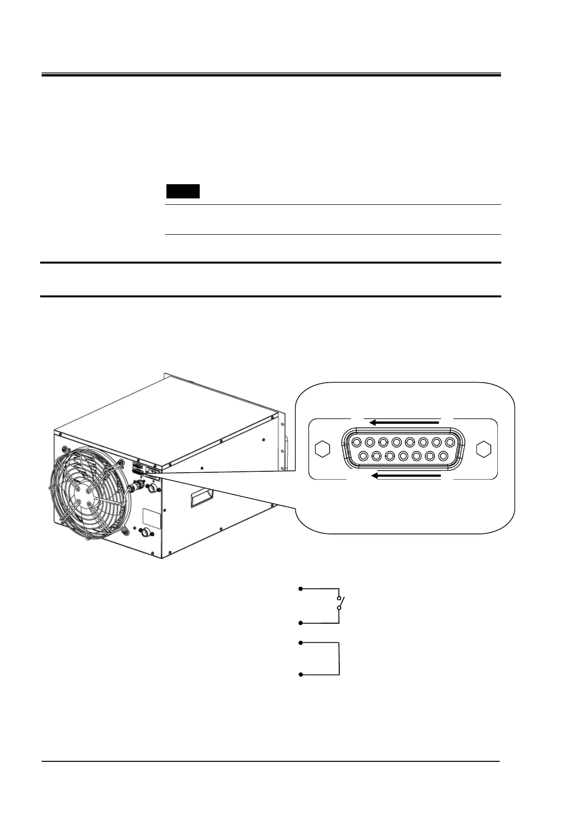
1. Prepare a suitable connector cable.
2. Wire the contact input / output signal connector as shown below and connect it to this
product.(This wiring is an example, please refer to the instruction manual
"Communication function" for details.)
Fig 3-6 Wiring of run/stop signal input (Example)
Dsub 15 pin female (socket) type
Contact input/output signal connector

 Loading...