HRX-OM-W002-A
Chapter 3 Transport and Setting Up
HRR Series 3.3 Installation
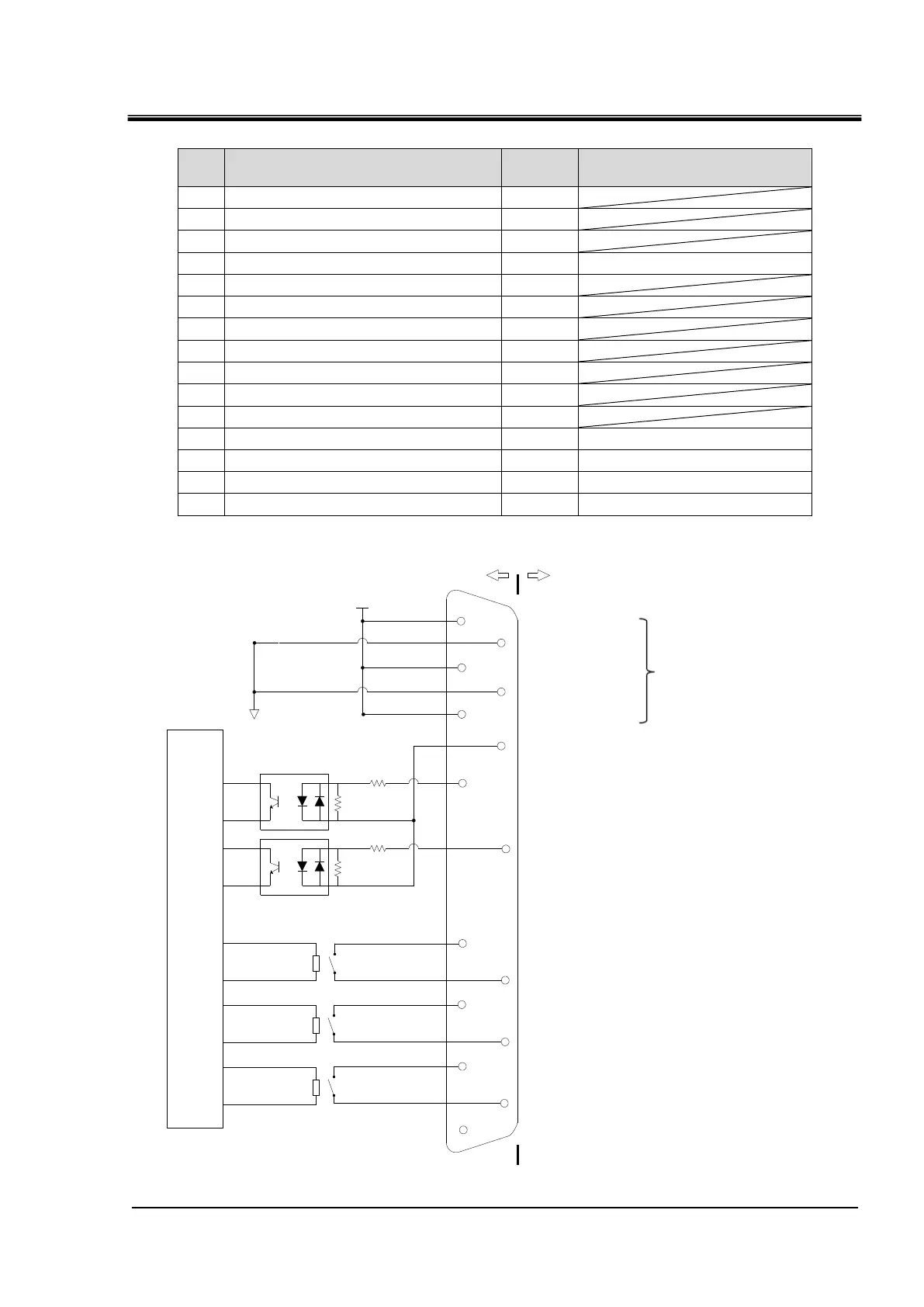
Table 3-6 Contact input/output pin number
Initial value
(Default setting)
COM of contact output signal 1
COM of contact output signal 2
COM of contact output signal 3
COM of contact input signal
Run status signal (N.O type)
Internal
circuit
1kΩ
4.7kΩ
1kΩ
4.7kΩ
11
4
12
6
14
7
15
8
5
13
3
10
2
9
1
DC24V
24COM
This product Your system
DC24V output
24COM output
DC24V output
24COM output
DC24V output
MAX 0.5A
COM of contact input signal
Contact input signal 1:OFF
(Default unsetting)
Contact input signal 2:OFF
(Default unsetting)
COM of contact output signal 1
Contact output signal 1:Run status
(Default unsetting)
COM of contact output signal 2
Contact output signal 2:Remote
(Default unsetting)
COM of contact output signal 3
Contact output signal :Alarm
(Default unsetting)
None
Fig 3-5 Contact input/output

 Loading...