HRX-OM-W002-A
Chapter 3 Transport and Setting Up
HRR Series 3.3 Installation
Wiring of interface communication cable
Connecting to PC
RS-485 cannot be directly connected to a normal PC. Use an RS-232C/RS485 converter which is
available on the market.
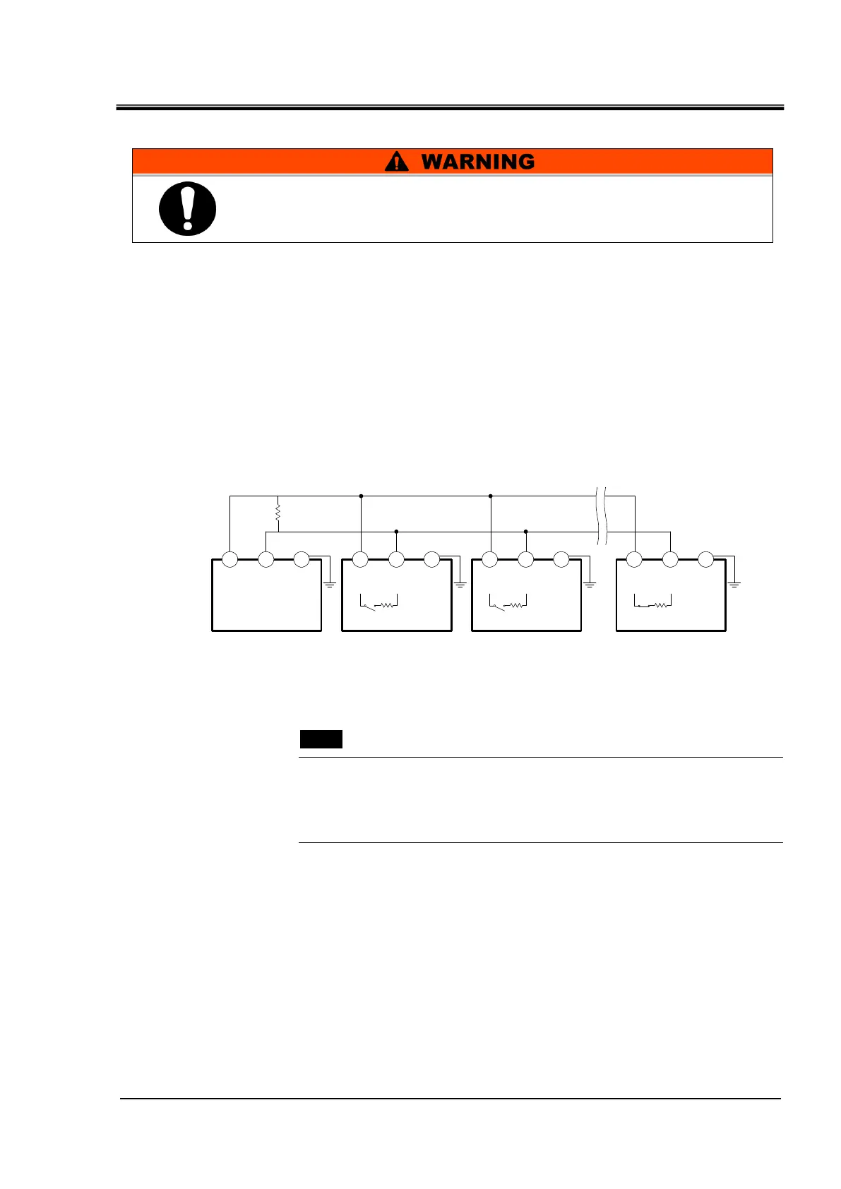
Be sure to follow the wiring procedure shown below for connecting multiple thermo-chillers.
Configuration of connection
One thermo-chiller for one host computer, or multiple thermo-chillers for one host
computer.(31 thermo-chillers can be connected at maximum.)
Fig 3-7 Connection of RS-485
[Tips]
Both ends of the communication connection (the end nodes) need to be
connected to the host computer.
With or without the terminating resistor of this product can be set by the
operation display panel. Refer to “5.5.5 Communication setting menu”
Be sure to turn OFF the breaker of the facility power supply (the
user's machine power supply) before wiring.
1
SD+
5
SG
9
SD-
SD+
SD- SG
Terminal
resistance
Master This product
(first slave)
1
SD+
5
SG
9
SD-
This product
(second slave)
1
SD+
5
SG
9
SD-
This product
(31
st
slaves)
Terminal
resistance120Ω

 Loading...