HRX-OM-X010
Chapter 5 System Operation
HRZ Series 5.3 Operation Screen
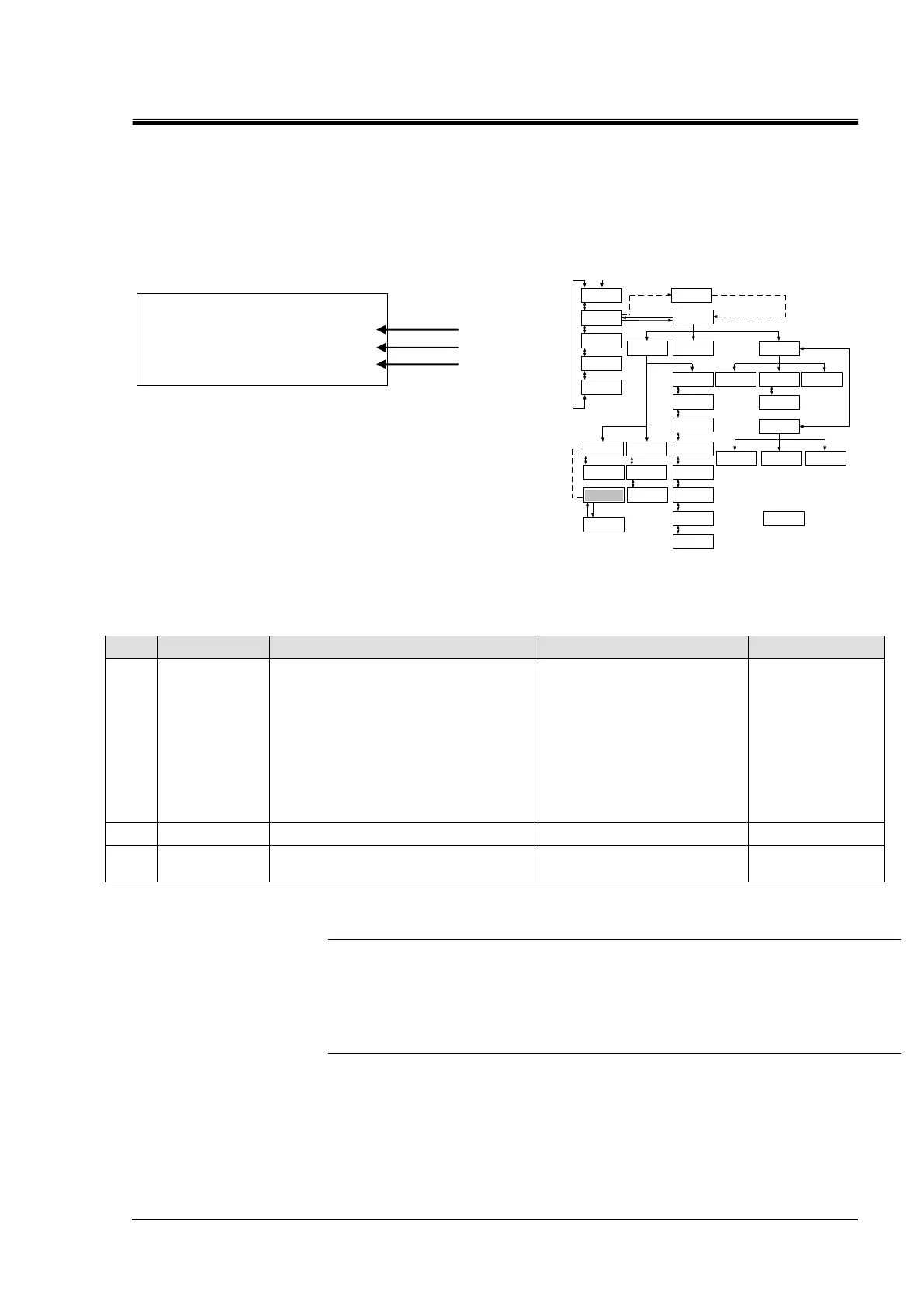
5.3.11 Control Setting screen 3-1
This screen is displayed if the PUMP IV is set to FREQ on the Initial Setting screen 3.
If PUMP IV is set to PRESS or FLOW, this screen will not be displayed and 5.3.9 Control Setting
screen 1 (page 5-11) will be displayed.
Figure 5-14 Control Setting screen3-1
Table 5-11 Control Setting screen3-1
Allows the setting of circulating
fluid discharge temperature.
HRZ002-WS/W1S-F:
-10.0 to 90.0 deg C
HRZ004/008/010-WS/W1S-F:
-20.0 to 90.0 deg C
HRZ***-W2S-F :
10.0 to 60.0 deg C
HRZ008-L/L1-F :
-20.0 to 40.0 deg C
Allows the setting of OFFSET value
*
1
Switched to the “Control Setting screen
3-2”.(Pump frequency setting screen.)
[Tips]
In the case of using Offset Function, select any one of MODE 1 to 3 on No.3 of
“Initial Setting screen 1”. See ”Chapter 8 8.4Offset Function“ (page 8-14) for details
(*1).
[▲] or [▼] key is used for selecting “Item.” And pressing [ENT] key enabling to
change the set point of TEMP SP and OFFSET.
<CONTROL SET> ↕
TEMP SP 25.0℃
OFFSET 0.0℃
PUMP SP 15.0Hz
 Loading...


