<(C40/C50) Input current
calibration
*
21
>
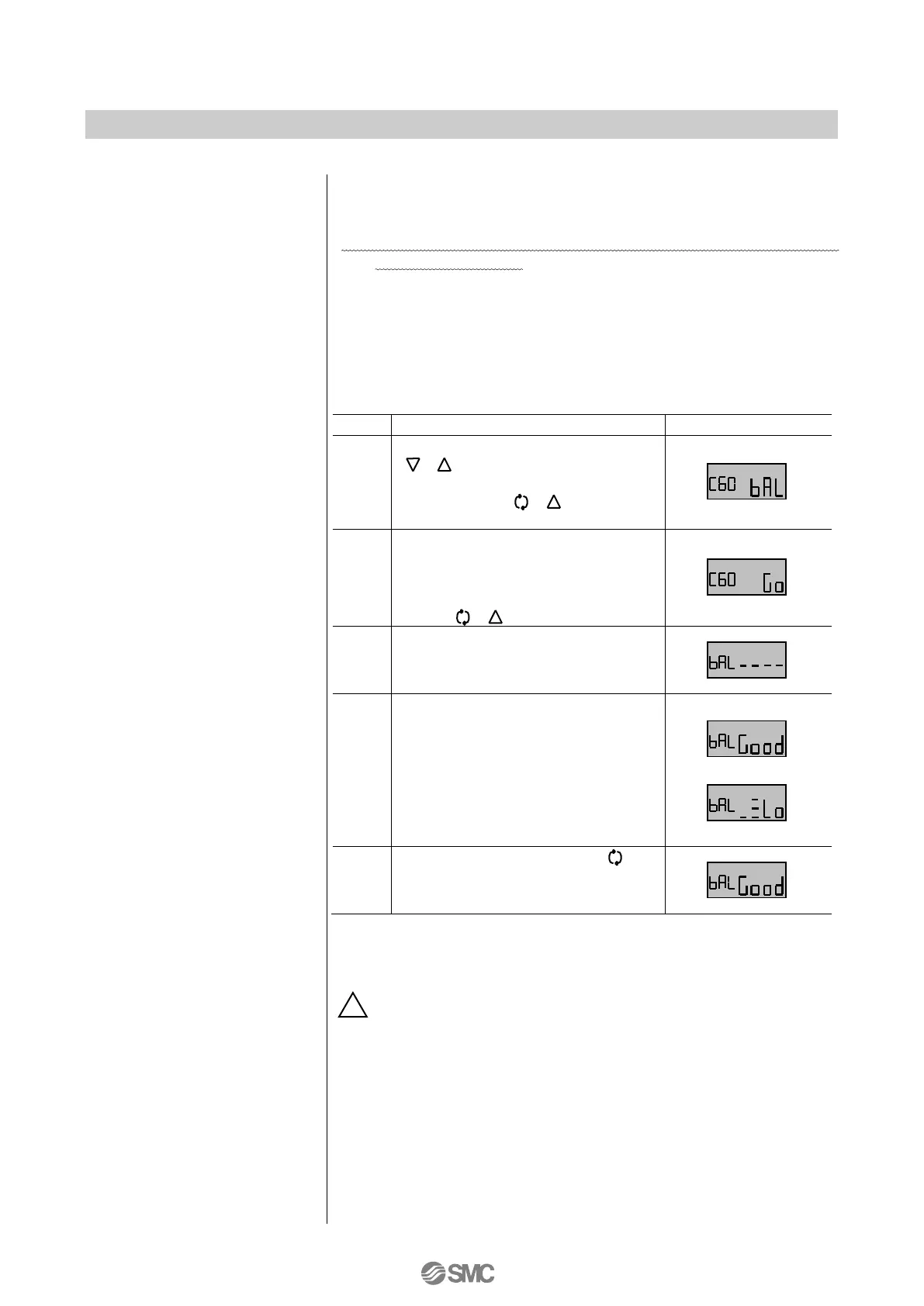
<(C60) Balance current
confirmation
*
22,
*
23
>
Check the torque motor balance current adjustment condition.
If adjustment is good (Good), balance current is correctly
adjusted. If high (HI) or low (Lo), readjustment is necessary so
that the balance current condition becomes good (Good).
Hold down Down or Up button
( ) at calibration mode. After
selecting balance (bAL), hold down
the set button ( ) for 1sec. or
longer.
Go (Go) is displayed for
confirmation. After confirming that it
is not dangerous even if the
actuator operate, hold down the set
button ( )
*
24
.
During balance current
confirmation, bar (----) is displayed.
After the actuator stop operating,
LCD display is switched from bar
(----). When good (Good) is
displayed, balance current is
correctly adjusted. If high (HI) or
low (Lo) is displayed, readjust the
current value by rotating the
balance adjusting screw
*
25,
*
26
.
Press the mode button ( ) to
return calibration mode selection
display.
22: This adjustment becomes available only after initial adjustment.
23: This function may not work due to hunching if user change PID
constant.
24: The actuator operate abruptly after holding down the button. Do not
touch the actuator and positioner.
25: See fig.19 for the balance adjusting screw location.
26: 1 to 6 bars (-) are displayed to the side of high (HI) or low (Lo). The
number of bars tells how close the current adjustment is to good
(Good); Six bars is closest, and one bar is furthest. Rotate the
balance adjusting screw clockwise for high (HI) and
counterclockwise for low (Lo) until good (Good) displays. When the
balance adjusting screw is turned, bars (----) show up to check the
adjustment condition. Do not turn the balance adjustment screw
until the condition is decided.
4mADC and 20mADC of input current can be calibrated. This is
not necessary usually.
21: For adjustment procedure, see “5. Input current calibration” of
“■Initial Adjustment”.

 Loading...