- 11 -
No.SFOD-OMT0010-B
3.2. Mounting the controller
Refer to
4.4 Mounting
for instructions on how to mount the controller.
3.3 Install the setting software and the driver
Install the controller setting software and driver software on the PC to be used.
For details, refer to the Installation Manual for the controller setting software (No.SFOD-OMT0008).
3.4 Wiring and connection
Connect the cables to the controller.
Refer to section
2.3 Product configuration
,
5.2 Wiring
and
6.4 Parallel I/O Wiring Example
for
wiring details.
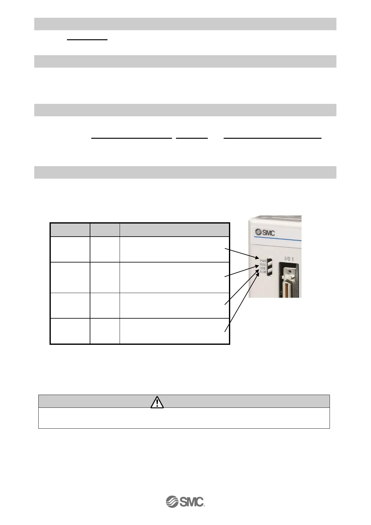
3.5 Power supply, Start-up of controller setting software, and Alarm check
(1) Supplying power
After supplying power for the motor control and motor drive, turn on the power supply for the main
control.
Check that thePWR LED is ON.
If the green PWR LED is not ON, check the wiring of the power supply and the power supply
voltage.
After supplying power for the motor control and motor drive, turn on the power supply for the
main control. Otherwise a“Modbus Error”alarm will be generated.

 Loading...


