- 26 -
No.SFOD-OMT0010-B
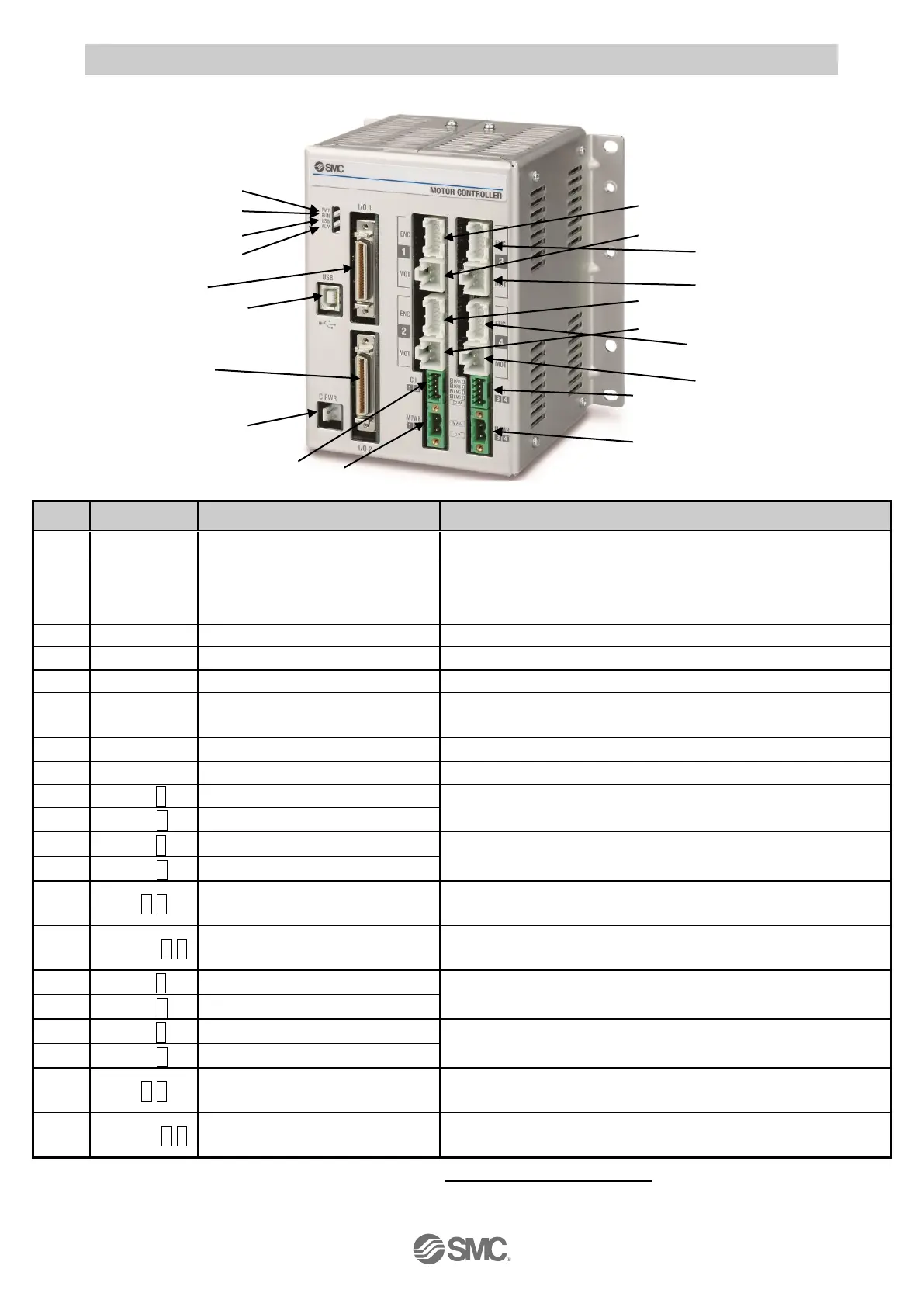
4.2 Parts Description
Detail of the controller parts.
Power supply ON: LED is ON Power supply OFF: LED is OFF
Operation by parallel I/O: LED is ON
Operation by USB communication: LED is Flashing
Stop: LED is OFF
Stop: Light off
USB connected: LED is ON USB not connected: LED is OFF
Alarm condition: LED is ON No alarm: LED is OFF
Connect to a PC using a USB cable.
Main control power supply
connector (2 pin)
Note)
Main control power supply (+)(-)
Parallel I/O connector (40 pins)
Connect to the PLC using an I/O cable.
Parallel I/O connector (40 pins)
Connect to the PLC using an I/O cable.
Encoder connector (16 pins)
Axis 1: Connect the actuator cable.
Motor power connector (6 pins)
Encoder connector (16 pins)
Axis 2: Connect the actuator cable.
Motor power connector (6 pins)
Motor control power supply
connector
Note)
Motor control power supply(+), Axis 1 stop(+), Axis 1 unlock(+), Axis 2
stop(+), Axis 2 unlock (+)
Motor drive power connector
Note)
Axis 1, Axis 2 Motor drive power (+), common(-)
Encoder connector (16 pins)
Axis 3: Connect the actuator cable.
Motor power connector (6 pins)
Encoder connector (16 pins)
Axis 4: Connect the actuator cable.
Motor power connector (6 pins)
Motor control power supply
connector
Note)
Motor control power supply(+), Axis 3 stop(+), Axis 3 unlock(+), Axis
4 stop(+), Axis 4 unlock (+)
Motor drive power connector
Note)
Axis 3, Axis 4 Motor drive power (+), common(-)
Note) The connector is included
.
Refer to section
5. Power supply connector
.

 Loading...


