2 Introduction
2.1 Basic Features
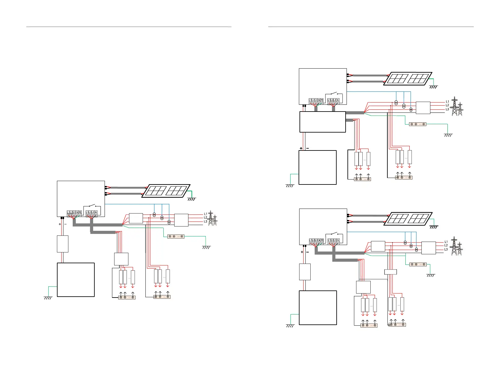
2.2 Electrical Block Diagram of the System
Diagram A: N line and PE line separate wiring, D series inverter;
(For most countries)
IntroductionInstallation
12
13
Diagram B: N line and PE line separate wiring, M series inverter;
(For most countries)
Diagram C: N line and PE line together, D series inverter;
( Applicable to Australia)
N
BAT
Battery
N-BAR for loads
N-BAR for EPS(Off-grid) loads
EPS(Off-grid) loads
Loads
Inverter
PV 1
PV 2
E-BAR
RCD
Breaker
Grid
Breaker
Grid
EPS(Off-grid)
Main Breaker/RCD
Breaker
Breaker
CT
Distribution Box
CT-R
CT-S
CT-T
N
BAT
Battery
N-BAR for loads
N-BAR for EPS(Off-grid) loads
EPS(Off-grid) loads
Loads
Inverter
PV 1
PV 2
E-BAR
RCD
Breaker
Grid
Breaker
Grid
EPS(Off-grid)
Main Breaker
Breaker
Breaker
CT
Distribution Box
N
CT-R
CT-T
CT-S
RCD
X3-Matebox
N
BAT
Battery
N-BAR for loads
N-BAR for EPS(Off-grid) loads
EPS(Off-grid) loads
Loads
Inverter
PV 1
PV 2
E-BAR
Grid
Grid
EPS(Off-grid)
Main Breaker/RCD
Breaker
Breaker
CT
CT-R
CT-S
CT-T
Distribution Box
The inverter has two wiring schemes, one is for M series
inverter connected to X3-Matebox, and the other is for D series
inverter.
There are different ways of wiring in different countries, one is to
connect N line with PE line, the other is to separate the line from
the PE line wiring, see below;
This high-quality inverter can convert solar energy into
alternating current and store energy into batteries.
The inverter can be used to optimize self-consumption, stored in
batteries for future use or fed into the public grid. The way it
works depends on user preferences. It can provide emergency
power during power outages.

 Loading...


