COM communication interface is mainly provided for customization the
second step of development use.The inverter supports the control of
external equipment or external equipment control through
communication.
For example, the inverter adjusts the working mode of the heat pump
and so on.
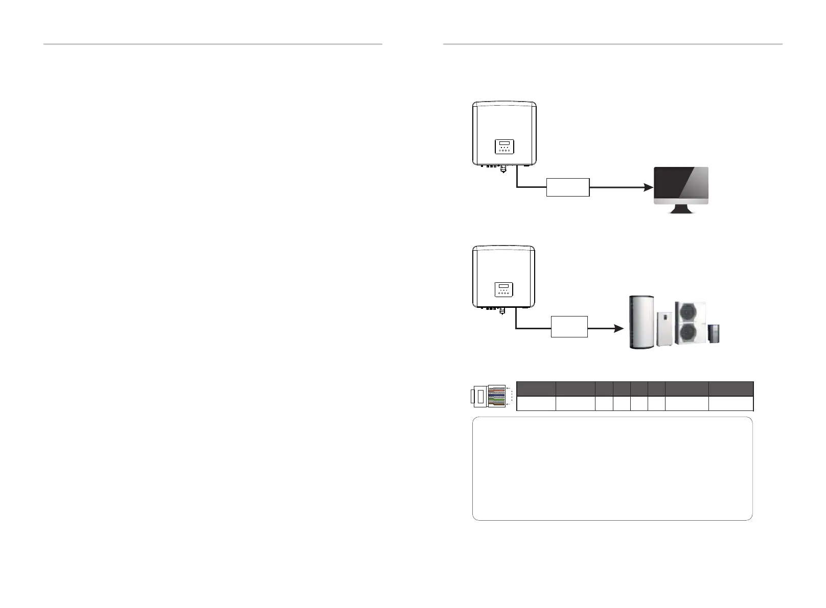
Ø COM PIN Definition
Ø Application occasion
COM is a standard communication interface, through which the
monitoring data of the inverter can be directly obtained. Also, external
communication devices can be connected to carry out the secondary
development of the inverter. For specific technical docking, please
contact us.
Electrical Connection
Electrical Connection
5.5.4 COM Communication
Note!
Customers can communicate or control the inverter and external
devices through the COM interface. Professional users can use
pins 4 and 5 to realize data acquisition and external control
functions. The communication protocol is Modbus RTU. For
details, please contact us. If the user wants to use the inverter dry
contact to control external equipment (such as a heat pump), it
can be used with our's Adapter Box. For details, please refer to the
Quick Installation Manual of the Adapter Box.
1 2 3 4 5 6 7 8
1
8
485A
485B
GND
Drycontact_A(in) Drycontact_B(in) Drycontact_A(out)
Drycontact_B(out)
+13V
External communication equipment controls the inverter:
Inverter communication control external equipment:
60
61
Date Read
Adapter
Box
Once slave inverter exit from system and be running as an independent
unit, its all setting will be re-excuted.
The rest of this section covers several important parallel control functions,
and the next page table shows which LCD options are controlled by
master inverter and which can work independently.
Off mode setting:
Off mode can only be set by master inverter ( long press ESC button on
LCD ).
Safety setting:
System safety protection is cancelled by master inverter’s safety. slave
inverter protection mechanism will only be triggered by master
inverter’s instructions.
Self-use setting:
If system is running as self-use mode, please note the Feedin Power Limit
set of master inverter is for the overall system and the corresponding set
of slave inverter is invalid.
Power Factor setting:
All sets about power factor are all for the overall system and the
corresponding sets of slave inverter are invalid.
Remote control setting:
The remote demand instructions received by master inverter will be
interpreted as the demand instructions to overall system.
External ATS setting:
INCORRECT line sequence (R-R, S-S, T-T, N-N) will damage the inverter. To
avoid the damage, the default “Disable” has been set to “Enable” in
“External ATS” under “Advance Settings”. Users should set the default
setting back to “Disable”. Because only when a matebox advanced is
connected, External ATS needs to be set to “Enable”.
USB to RS-485
converter

 Loading...


