Electrical Connection
Electrical Connection
a) Check that the inverter is well xed on the wall.
b) Ensure that all ground wires are well tightened.
c) Ensure that all DC and AC circuit breakers are disconnected.
d) Ensure that all ground wires are well tightened.
e) The AC output terminal is correctly connected to the mains.
f ) Ensure that all photovoltaic panels and inverters are properly
connected. Unused DC connectors should be blocked with caps.
The following are 3 different states of inverter operation, which
means that the inverter starts successfully.
Waiting: When the DC output voltage of the photovoltaic panel is higher
than 160V (lowest starting voltage) and lower than 180V (lowest working
voltage), the inverter waits for checking.
Checking: The inverter will automatically detect the DC input. When the
DC input voltage of the photovoltaic panel is higher than 200V and the
photovoltaic panel has enough energy to start the inverter, the inverter
will enter the checking state.
Steps to start the inverter
- Turn on the AC switch between the inverter and the power grid.
- (Optional) Remove the locking screw from the DC switch.
- Turn on the DC switch between the PV string and the inverter if
there is any.
- Turn on the DC switch at the bottom of the inverter .
When the photovoltaic panel generates enough power, the inverter
will start automatically.
- If the battery port of the inverter is connected to a battery, turn
on the auxiliary power switch of the battery and then the battery
switch.
Check the status of the LED and LCD screen, the LED is blue, and the
LCD displays the main interface.
If the LED is not blue, please check the following:
- All connections are correct.
- All external disconnect switches are closed.
- The DC switch of the inverter is set to the "ON" position.
Ø Before operation, check the inverter according to the
following steps
Ø Start the inverter
5.9 Inverter Operation
76
77
Warning!
The input terminal of the inverter can be opened only when all
the installation work of the inverter has been completed. All
electrical connections must be performed by professionals in
accordance with local regulations.
Normal: When the inverter is working normally, the green light is always
on. At the same time, the power is fed back to the grid, and the LCD
displays the output power.
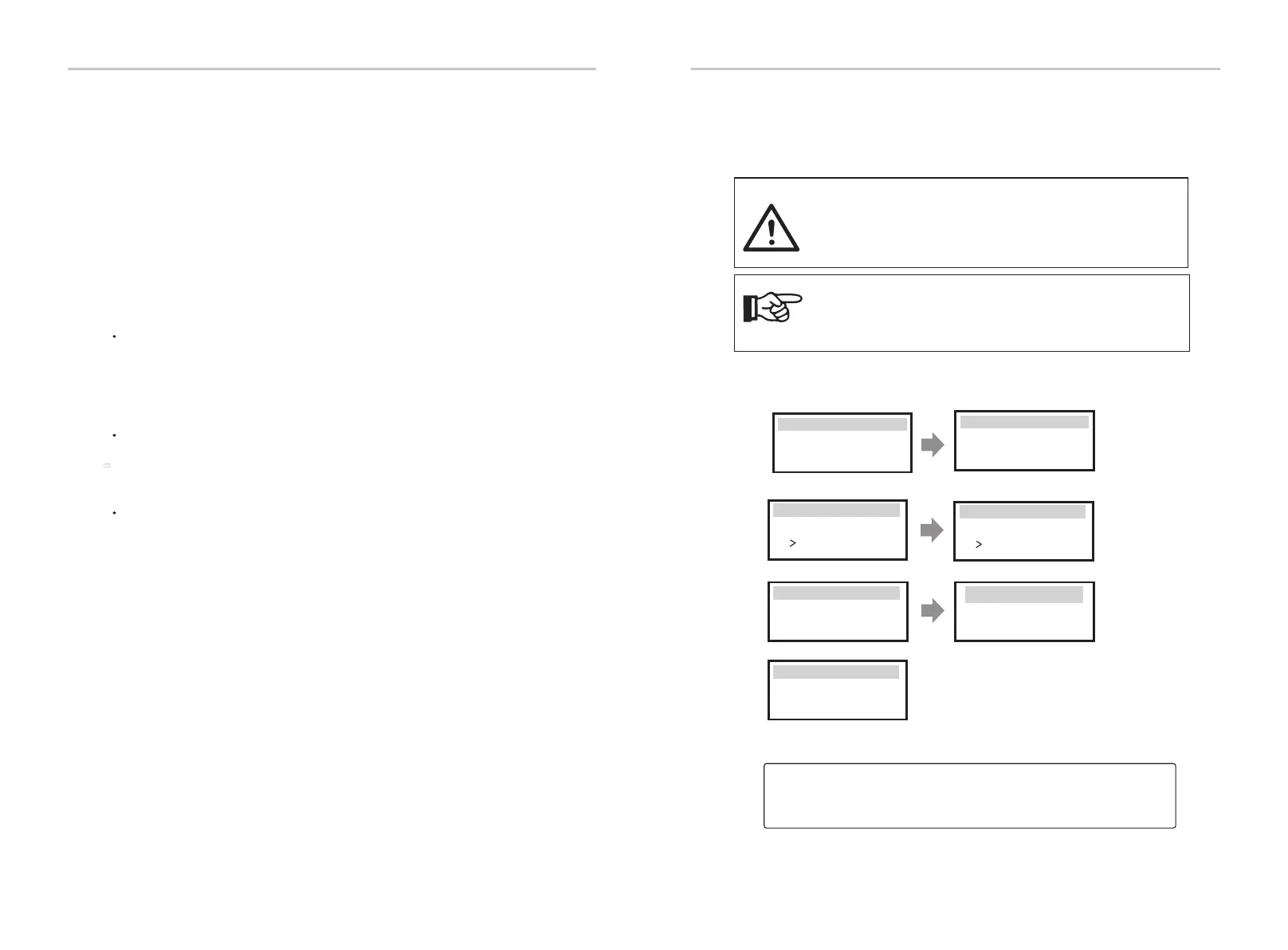
If it is the rst time to boot, please follow the prompts to enter the setting
interface.
Note!
If it is the first time to operate the inverter, the system will
automatically display setup guide. Please follow the setup guide
to complete the basic inverter settings.
English
Deutsch
Italian
Language
2.Set language
2021 ->11 <-10
10:05
Date time
1.Set date time
Country
VDE0126
Safety
3.Set the safety standard
CT
Meter
CT/Meter Setting
4.CT/Meter Setting
Export control
Use Value:
10000W
Export Control
5 .Set export control*
Functional Control
Enable Disable
External ATS
7.External ATS
6 .Set work mode*
>Mode Select
self use
Work Mode
5*.Export Control
Please follow the setup guide to complete the basic inverter settings.
This function allows the inverter able to control energy exported to the grid.
There are user value and factory value. The factory value is default which can
not be charged by user. The user value set by installer must be less than the
factory value.

 Loading...


