5.5.3 Parallel Connection
Electrical Connection
Electrical Connection
54
55
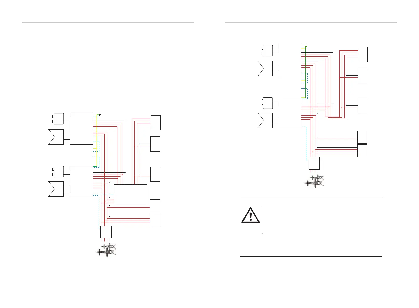
Ø System Diagram
Master
Slave
S
R
T N S T N
......
R
CAN CAN
Grid
PV+ PV- PV+ PV-
+ -
Battery
+ -
Battery
S
R
T
N
PE
PE
Meter
CAN
485
... ...
S
R
T N S
R
T N
Meter
S
T
N
R
EPS (Off-grid) EPS(Off-grid)
GridGrid
S
T
N
R
Inverter Inverter
single-phase
NormalLoad
three-phase
NormalLoad
NS
R
T NL
single-phase
Critical Load
NL
CANCAN
three-phase
Critical Load
N S
R
T
single-phase
Critical Load
NL
PE
Diagram 2
Ø Work Modes in Parallel System
Master
Slave
S
R
T N S T N
......
R
CAN CAN
Grid
PV+ PV- PV+ PV-
+ -
Battery
+ -
Battery
S
R
T
N
PE
PE
COM
Meter
CAN
485
... ...
S
R
T N S
R
T N
Meter
S
T
N
R
EPS (Off-grid) EPS
GridGrid
S
T
N
R
Inverter
Inverter
EPS
Load
single-phase
NormalLoad
three-phase
NormalLoad
NS
R
T NL
single-phase
Critical Load
NL
S
R
T N
Grid
CANCAN
three-phase
Critical Load
N S
R
T
single-phase
Critical Load
NL
PE
Diagram 1
X3-PBOX-60kW/
150kW-G2
Important Warning!
The hybrid parallel system is extremely complex and a large
amount cables need to be connected, therefore it is strongly
required that every cable must be connected according to
correct line sequence (R-R, S-S, T-T, N-N), otherwise any small
misoperation may cause the system running failed.
In diagram 2, INCORRECT line sequence (R-R, S-S, T-T, N-N) will
damage the inverter. To avoid the damage, the default
“Disable” has been set to “Enable” in “External ATS” under
"Advance Settings". Please set the default “Enable” in
“External ATS” back to “Disable”.
There are three work modes in parallel system, and your acknowledge
of different inverter’s work modes will help you understand parallel
system better, therefore please read it carefully before operating.
The inverter provides a parallel function. 10 inverters can be
maximally connected in diagram 1. And diagram 2 allows up to three
inverters to be connected. In these two systems, one inverter will be
set as the "master inverter" which controls every other "slave inverter"
in the system. In diagram 1, an X3-PBOX-150kW-G2 should be
equipped and connected to the "master inverter," "slave inverter 1"
should be connected to the "master inverter," and all other "slave
inverters" are connected via network cable in a numbered sequence.
An X3-PBOX-60kW-G2 can be selected when no more than six
inveters are paralleled in diagram 1 system.

 Loading...


