Electrical Connection
Electrical Connection
56
57
For diagram 2
slave1 Master
Meter
CAN1 CAN2 CAN1 CAN2
Meter
network cable
Inverter
slave2
Inverter
Inverter
network cable
Step1: Connect all inverters' communication together by connecting
network cables between CAN ports.
- Use standard network cables for CAN-CAN connection.
- Use network cable to connect master inverter CAN2 port and slave 1
inverter CAN1 port, and connect slave 1 inverter CAN2 port and slave2
inverter CAN1 port.
- Use network cable to connect master inverter meter port and meter.
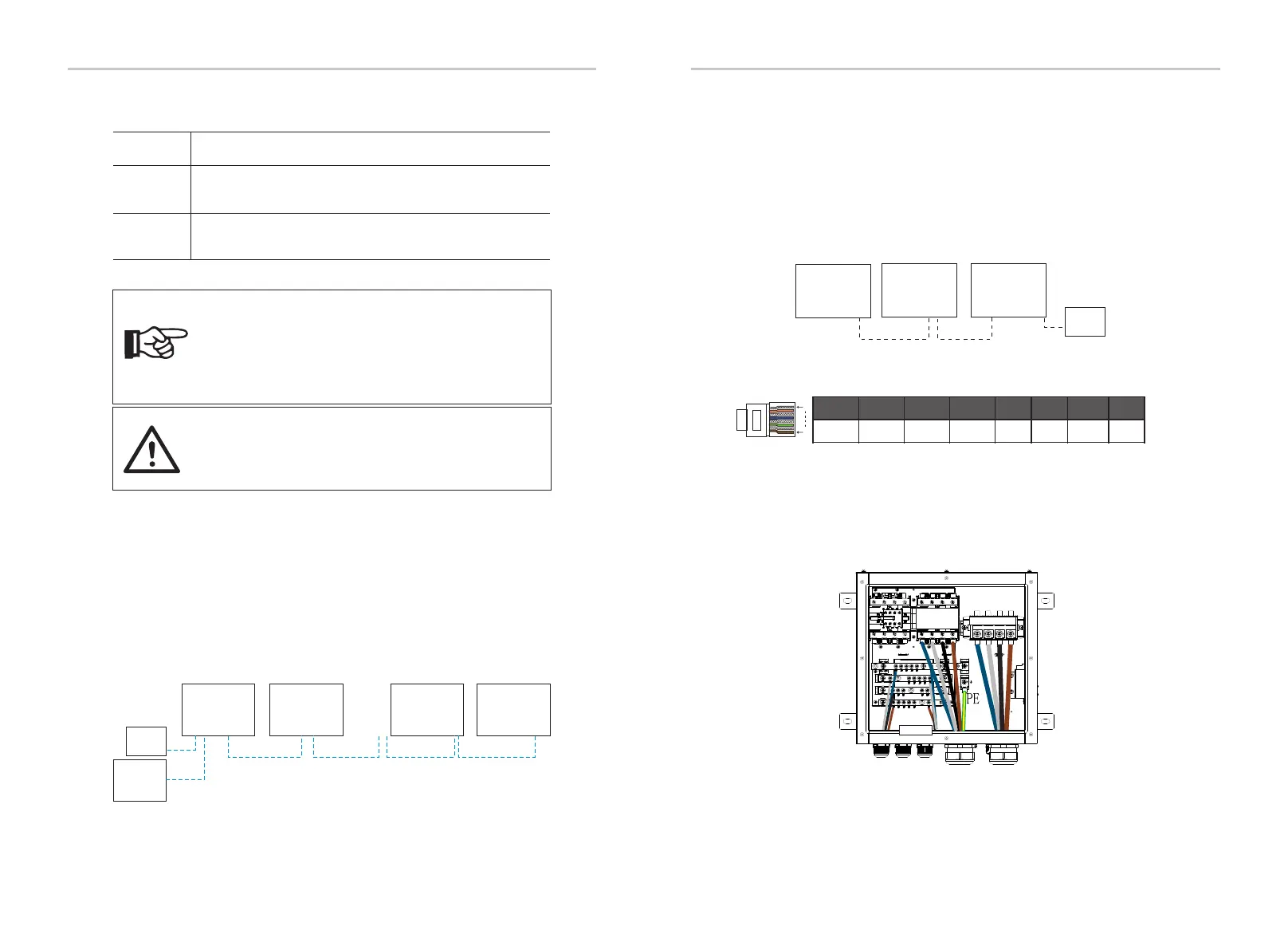
Ø CAN PIN Definition
SYN1
485A
SYN2CANL GNDCANHVCC
1 2 3 4 5 6 7 8
1
485B
Inverter
Master
Inverter
slave1
Inverter
slave8
Inverter
slave9
......
Meter
CAN(2)
CAN(2)
CAN(2)
CAN(1)
CAN(2)
Meter
X3-PBOX-60kW/
150kW-G2
CAN
(1)
COM
network cable
network
cable
CAN(1)
CAN(1)
CAN(1)
X3-PBOX-150kW-G2
For example, the wiring diagram of the X3-PBOX-150kW-G2 power line.
......
n=10
EPS
GRID
LOAD
N RT S
For diagram 1
Note: Before operation, please make sure that the inverter
meets the following three conditions,
1. The software version of all inverters is the same;
2. The power range of all inverter models is the same;
3. The type and quantity of batteries connected to all
inverters are the same;
Otherwise, this function cannot be used.
Ø Wiring Operation and LCD Setting
Note: There are two CAN ports on the inverter. The CAN
port of the inverter set as the "host" is connected. The CAN
port on the left on the bottom frame of the inverter must
be connected to the COM port of the X3-PBOX-60kW/
150kW-G2, and the CAN port on the right is connected "Slave".
Free mode
Master mode
Slave mode
Only if no one inverter is set as a “Master”, all inverters are in
free mode in the system.
When one inverter is set as a “Master”, this inverter enters
master mode.
Master mode can be changed to free mode.
Once one inverter is set as a “Master”, all other inverters will
enter slave mode automatically. slave mode can not be
changed from other modes by LCD setting.
Note:A CT can be used in the parallel connection of the Hybrid series
inverters only when the master inverter are with PV panels or only the
meter can be used. In the parallel connection of the Fit series inverters,
only the meter can be used.
Step1: Connect all inverters’ communication together by
connecting network cables between CAN ports.
- Use standard network cables for CAN-CAN connection and insert
one end of the cable into CAN1 of the master inverter and the other
end into the COM port of X3-PBOX-60kW/150kW-G2.
- Insert one end of network cable into the rst inverter’s CAN2 port
and the other end into the next inverter’s CAN1 port and other
inverters are connected in such way .
- Insert one end of network cable into the meter, and the other end
into the meter port the master inverter.
Step 2: Connect the power cable between X3-PBOX-60kW/150kW-
G2 and inverter (R/S/T/N/PE) in diagram 1.
-If the user purchased the X3-PBOX-60kW/150kW-G2 product, please
refer to the X3-PBOX-60kW/150kW-G2 user manual for installation
and connection.

 Loading...


