Step 1. Prepare a communication cable, and then find RJ 45 terminals in
the accessory bag.
Step 3. Insert the communication cable through the communication
adapter, and peel off the outer insulation layer of 15 mm.
Electrical Connection
Electrical Connection
5.5.5 Communication Connection Steps
Step 2 . The inverter CAN/DRM/OFF port communication line connection,
need to remove the inverter cover plate.
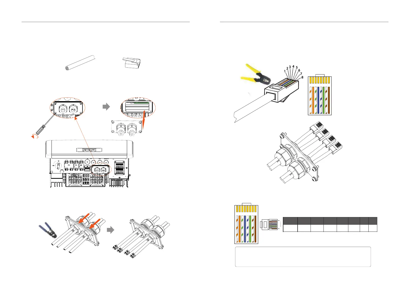
Step 4. Insert the prepared communication cables into the RJ45 terminals
in sequence, and then use network cable crimping pliers to press them tightly.
Communication cable
RJ 45 terminal
1
5
.
00
m
m
CAN
CAN
Shut down
DRM
Diagonal pliers
62
63
The DRM pin is defined as follows:
1 2
3
4
5
6 7 8
1) White with orange stripes
2) Orange
3) White with green stripes
4) Blue
5) White with blue stripes
6) Green
7) White with brown stripes
8) Brown
Multifunction terminal
crimping tool (RJ45)
Ø DRM communication cable
DRM4/8
+3.3V
DRM0
GND GND
DRM1/5 DRM2/6 DRM3/7
1 2 3 4 5 6 7 8
1
8
1 2
3
4
5
6 7 8
Note!
At present, there are only PIN6 (DRM0) and PINI (DRM1 /5), and
oher PIN functions are under development.
Gri d
EPS
CAN C AN LCD DR M
com
Torque screwdriver
(Torque: 1.2±0.1N·m)
Upg rade/ Dongl e

 Loading...


