Nucleus
2
User Guide Page 45
7. Analogue Operations
Nucleus
2
has two areas of analogue operation: the input section (used for recording sources to the DAW) and the
monitoring.
RECORDING SOURCES
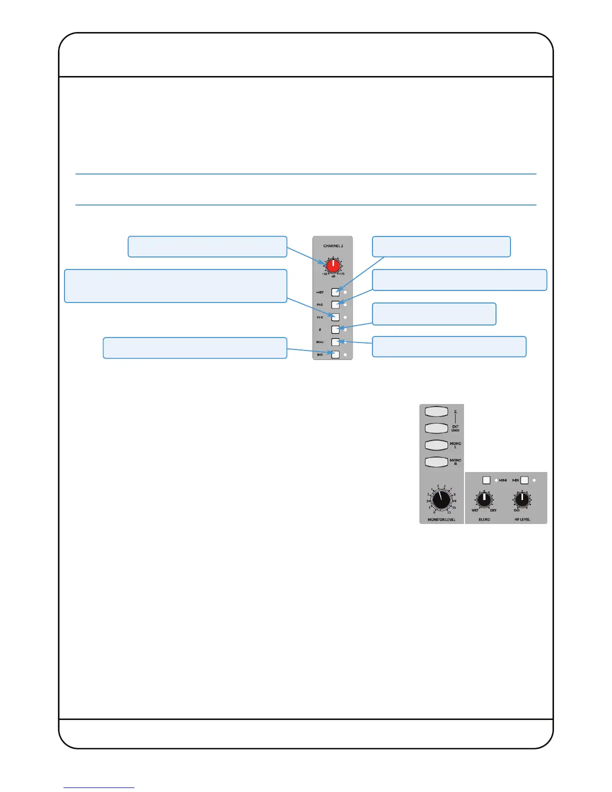
The input section of Nucleus
2
is located in the top right-hand corner of the centre section. There are two input channels,
with insert circuits for introducing external processing to the signal. The inputs have ‘combi’ connectors for plugging in
microphone XLRs or instrument jacks, and the inserts are on 1/4" jack plugs, all located on the Nucleus
2
back panel.
Note that the insert circuit can be sourced from the DAW outputs instead of the channel inputs by pressing the
MIX
button below the input area. See the following page for details.
The input controls are as follows:
MONITORING
The Nucleus
2
monitoring is controlled using the source selector switches to the right, and the controls beneath, the input
section.
The level of the main monitors is controlled by turning the MONITOR LEVEL control in
the centre of the centre section. The MINI button switches the main monitor outputs
to the MINI monitor outputs.
The headphone level is controlled independently using the HP LEVEL control below
CHANNEL .
Normally, the monitor and headphone outputs receive a mix of the inputs to Channels
1 and 2 and the DAW return, allowing for true zero latency monitoring. The mix between
the two is adjusted using the BLEND control below CHANNEL ; to hear more of the
inputs turn it towards DRY, and to hear more of the computer, turn it towards WET.
By default, the monitoring treats the channel inputs as a single stereo input, with Channel 1 fed to the left monitor stem,
and Channel 2 fed to the right. Press the MONO L and MONO R switches above the MONITOR LEVEL control to treat the
channel inputs as mono:
- With MONO L selected, the signal from Channel 1 will be sent to both sides of the monitors and Channel 2 will be muted.
- With MONO R selected, the signal from Channel 2 will be sent to both sides of the monitors and Channel 1 will be
muted.
- With MONO L and MONO R selected, the signals from both Channels will be sent to both sides of the monitors.
Activates +V Phantom power
Introduces a –20dB PAD (gain reduction)
Ø inverts the signal’s phase
Introduces an HZ high-pass filter
Input Level Control (+12dB to +75dB)
HIZ switches the XLR (microphone) input from low
to high impedance (Jack input is always high impedance.)
Switch the insert circuit in by pressing INS