SN8P2624
8-Bit Micro-Controller
SONiX TECHNOLOGY CO., LTD Page 47 Version 0.3
4.3 OSCM REGISTER
The OSCM register is an oscillator control register. It controls oscillator status, system mode.
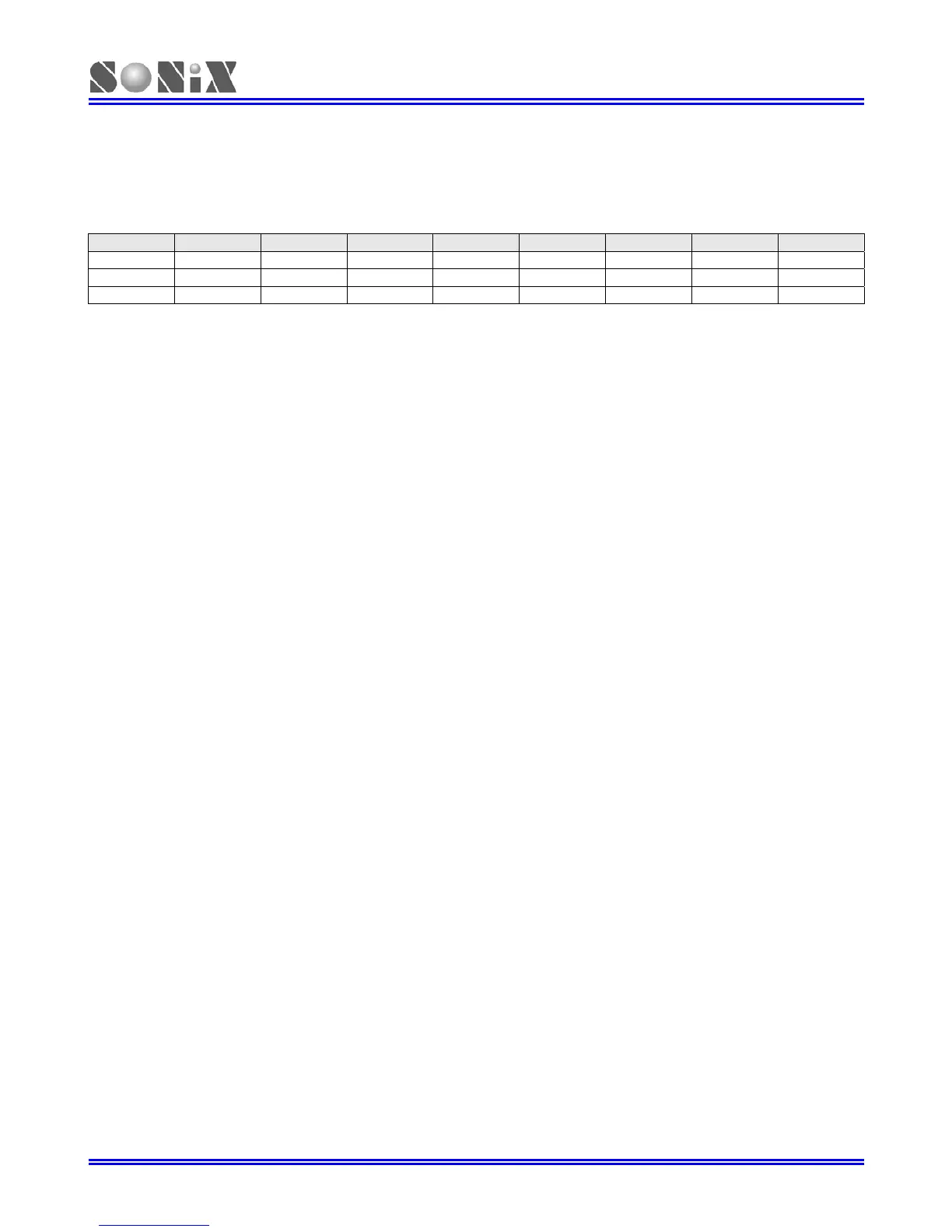
0CAH Bit 7 Bit 6 Bit 5 Bit 4 Bit 3 Bit 2 Bit 1 Bit 0
OSCM
0 0 0 CPUM1 CPUM0 CLKMD STPHX 0
Read/Write - - - R/W R/W R/W R/W -
After reset - - - 0 0 0 0 -
Bit 1 STPHX: External high-speed oscillator control bit.
0 = External high-speed oscillator free run.
1 = External high-speed oscillator free run stop. Internal low-speed RC oscillator is still running.
Bit 2 CLKMD: System high/Low clock mode control bit.
0 = Normal (dual) mode. System clock is high clock.
1 = Slow mode. System clock is internal low clock.
Bit[4:3] CPUM[1:0]: CPU operating mode control bits.
00 = normal.
01 = sleep (power down) mode.
10 = green mode.
11 = reserved.
¾ Example: Stop high-speed oscillator
B0BSET FSTPHX ; To stop external high-speed oscillator only.
¾ Example: When entering the power down mode (sleep mode), both high-speed oscillator and internal
low-speed oscillator will be stopped.
B0BSET FCPUM0 ; To stop external high-speed oscillator and internal low-speed
; oscillator called power down mode (sleep mode).