SN8P2624
8-Bit Micro-Controller
SONiX TECHNOLOGY CO., LTD Page 67 Version 0.3
7
7
7
I/O PORT
7.1 I/O PORT MODE
The port direction is programmed by PnM register. All I/O ports can select input or output direction.
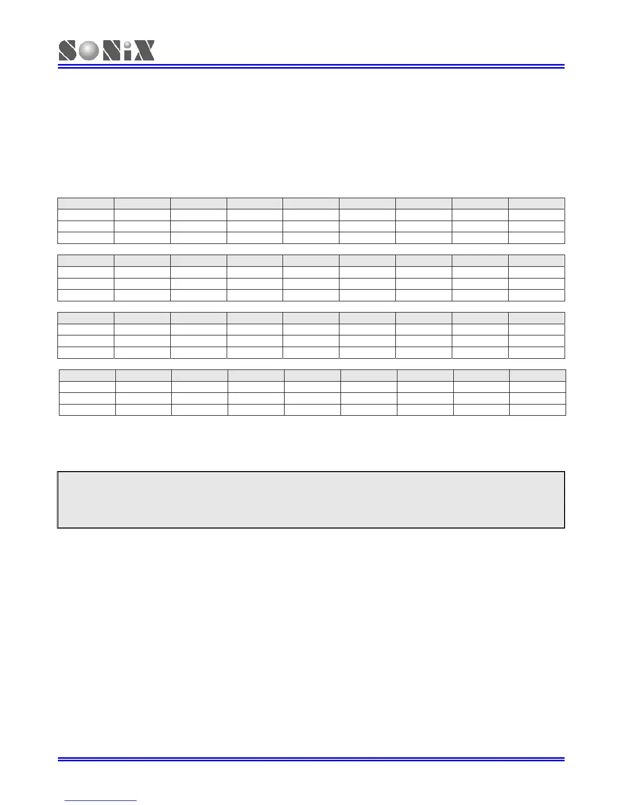
0B8H Bit 7 Bit 6 Bit 5 Bit 4 Bit 3 Bit 2 Bit 1 Bit 0
P0M
- - - - - - P01M P00M
Read/Write - - - - - - R/W R/W
After reset - - - - - - 0 0
0C1H Bit 7 Bit 6 Bit 5 Bit 4 Bit 3 Bit 2 Bit 1 Bit 0
P1M
P17M P16M P15M P14M P13M P12M P12M P10M
Read/Write R/W R/W R/W R/W R/W R/W R/W R/W
After reset 0 0 0 0 0 0 0 0
0C2H Bit 7 Bit 6 Bit 5 Bit 4 Bit 3 Bit 2 Bit 1 Bit 0
P2M
P27M P26M P25M P24M P23M P22M P22M P20M
Read/Write R/W R/W R/W R/W R/W R/W R/W R/W
After reset 0 0 0 0 0 0 0 0
0C5H Bit 7 Bit 6 Bit 5 Bit 4 Bit 3 Bit 2 Bit 1 Bit 0
P5M
- - - P54M P53M P52M P51M P50M
Read/Write - - - R/W R/W R/W R/W R/W
After reset - - - 0 0 0 0 0
Bit[7:0] PnM[7:0]: Pn mode control bits. (n = 0~5).
0 = Pn is input mode.
1 = Pn is output mode.
Note:
1. Users can program them by bit control instructions (B0BSET, B0BCLR).
2. P0.2 is input only pin, and the P0M.2 keeps “1”.
¾ Example: I/O mode selecting
CLR P0M ; Set all ports to be input mode.
CLR P2M
CLR P1M
CLR P5M
MOV A, #0FFH ; Set all ports to be output mode.
B0MOV P0M, A
B0MOV P1M, A
B0MOV P2M, A
B0MOV P5M, A
B0BCLR P1M.2 ; Set P1.2 to be input mode.
B0BSET P1M.2 ; Set P1.2 to be output mode.