SN8P2624
8-Bit Micro-Controller
SONiX TECHNOLOGY CO., LTD Page 53 Version 0.3
5
5
5
SYSTEM OPERATION MODE
5.1 OVERVIEW
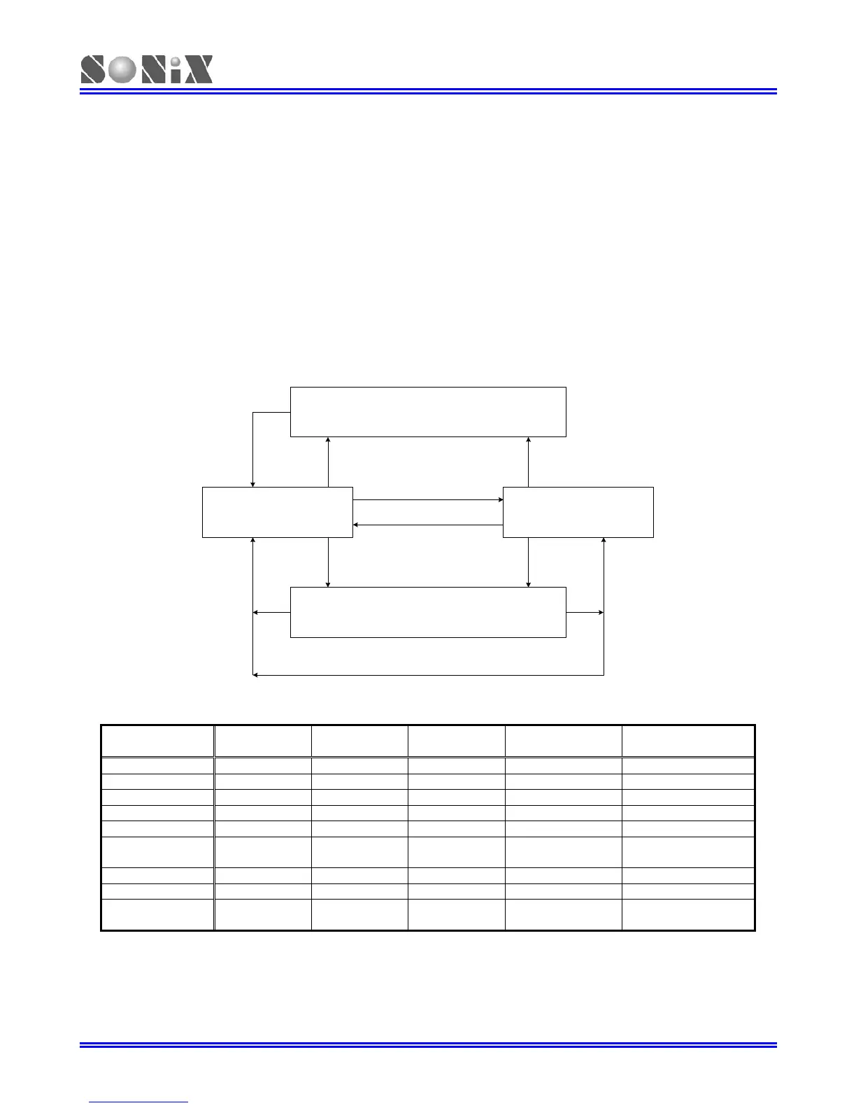
The chip is featured with low power consumption by switching around four different modes as following.
z Normal mode (High-speed mode)
z Slow mode (Low-speed mode)
z Power-down mode (Sleep mode)
z Green mode
Power Down Mode
(Sleep Mode)
Slow Mode
Green Mode
Normal Mode
CLKMD = 1
CLKMD = 0
P0, P1 Wake-up Function Active.
External Reset Circuit Active.
CPUM1, CPUM0 = 01.
CPUM1, CPUM0 = 10.
P0, P1 Wake-up Function Active.
T0 Timer Time Out.
External Reset Circuit
Active.
P0, P1 Wake-up Function Active.
T0 Timer Time Out.
External Reset Circuit Active.
System Mode Switching Diagram
Operating mode description
MODE NORMAL SLOW GREEN
POWER DOWN
(SLEEP)
REMARK
EHOSC Running By STPHX By STPHX Stop
ILRC Running Running Running Stop
CPU instruction Executing Executing Stop Stop
T0 timer *Active *Active *Active Inactive * Active if T0ENB=1
TC1 timer *Active *Active *Active Inactive * Active if TC1ENB=1
Watchdog timer
By Watch_Dog
Code option
By Watch_Dog
Code option
By Watch_Dog
Code option
By Watch_Dog
Code option
Refer to code option
description
Internal interrupt All active All active T0, TC1 All inactive
External interrupt All active All active All active All inactive
Wakeup source - -
P0, P1, T0
Reset
P0, P1, Reset
EHOSC: External high clock
ILRC: Internal low clock (16K RC oscillator at 3V, 32K at 5V)