2-3 (E)
CA-550
CA-550P
• Viewfinder Screen
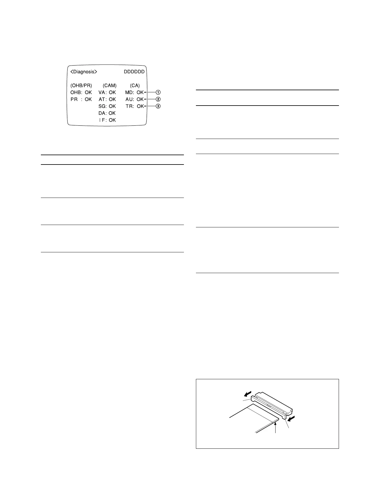
• Display Descriptions
Marks Board Judging Point Expected Abnormality
1 MD-103 Y RF output • RF carrier levels for Y
Color-difference and R-Y/B-Y are out of
RF output specs. *
• Improper connection of
the board
2 AU-211 +7.5 V and • Power voltage for the
INCOM +7.5 V board is out of specs. *
• Improper connection of
the board
3 TR-90 RF output (TP3) • Carrier level for AUDIO
RF is out of specs. *
• Improper connection of
the board
* Only when no video signal is input.
n
When the CA-550/550P is not connected to the CCU, the
columns 1 through 3 will display “– –”.
Refer to BVP-550/550P maintenance manual for descrip-
tions on columns of BVP and OHB.
2-5. Extension Boards
The extension boards and harness are available separately
for check or adjustment of some printed circuit boards.
Extension
Board/ Harness Sony P/N To be extended
EX-464 J-6395-040-A MD-103
AU-211
TR-90
Plug-in boards for
BVP-550/550P
EX-511 J-6395-020-A DM-98
DM-99 (option)
2-6. Disconnecting/Connecting Flexible
Card Wire
The two flexible card wires are used between the MB-605
and CN-1190 boards. Take care not to break these flexible
card wires. This shorten the wire life.
Disconnecting
1. Turn off the power.
2. Slide portions A in the direciton of the arrow to unlock
and pull out the flexible card wire.
Connecting
m
• Be careful not to insert the flexible card wire obliquely.
• Check that the conductive surface of the flexible card
wire is not soiled with dust.
1. Slide portions A in the direction of the arrow and
insert the flexible card wire as far as it will go with the
conductive surface down.
2. Slide portions A in the reverse direction to lock.
2-4. Self-Diagnosis
2-5. Extension Boards
2-6. Disconnecting/Connecting Flexible Card Wire
A
Conductive
surface
A