3-7 (E)
CA-550
CA-550P
3-3-8. INCOM Demodulation Adjustment
Notes:
• This adjustment is necessary only when replacing T202
or T203 on the TR-90 board.
• Use a plastic core driver to adjust 1T.
Equipment : Oscilloscope Audio generator
Distortion meter
Preparations :
• INCOM level control/at the right-rear→ 2fully clock-
wise
• CCU-700/700P/700A/700AP setting
Extend the AT-88 board of the CCU.
S2081 (PGM IN 0 dB/-20 dB)/AT-88 (D-5)→ 0dB
S2082 (PGM MIX ON/OFF)/AT-88 (F-5)→ ON
Test Point : Pin 4 (X), Pin 3 (G)/
INCOM connector
Adjustment Procedures:
1. Feed an 1.0-kHz sine wave signal from the audio
generator to pins D68 (X), A69 (Y), and B69 (GND)
on the extension board (extending AT-88) referring to
Section 3-1-3 “Connection — For audio adjustments”.
2. Adjust the audio generator so that the level at TP44
(GND:E1)/AT-88 (L-7) is 200 mVp-p.
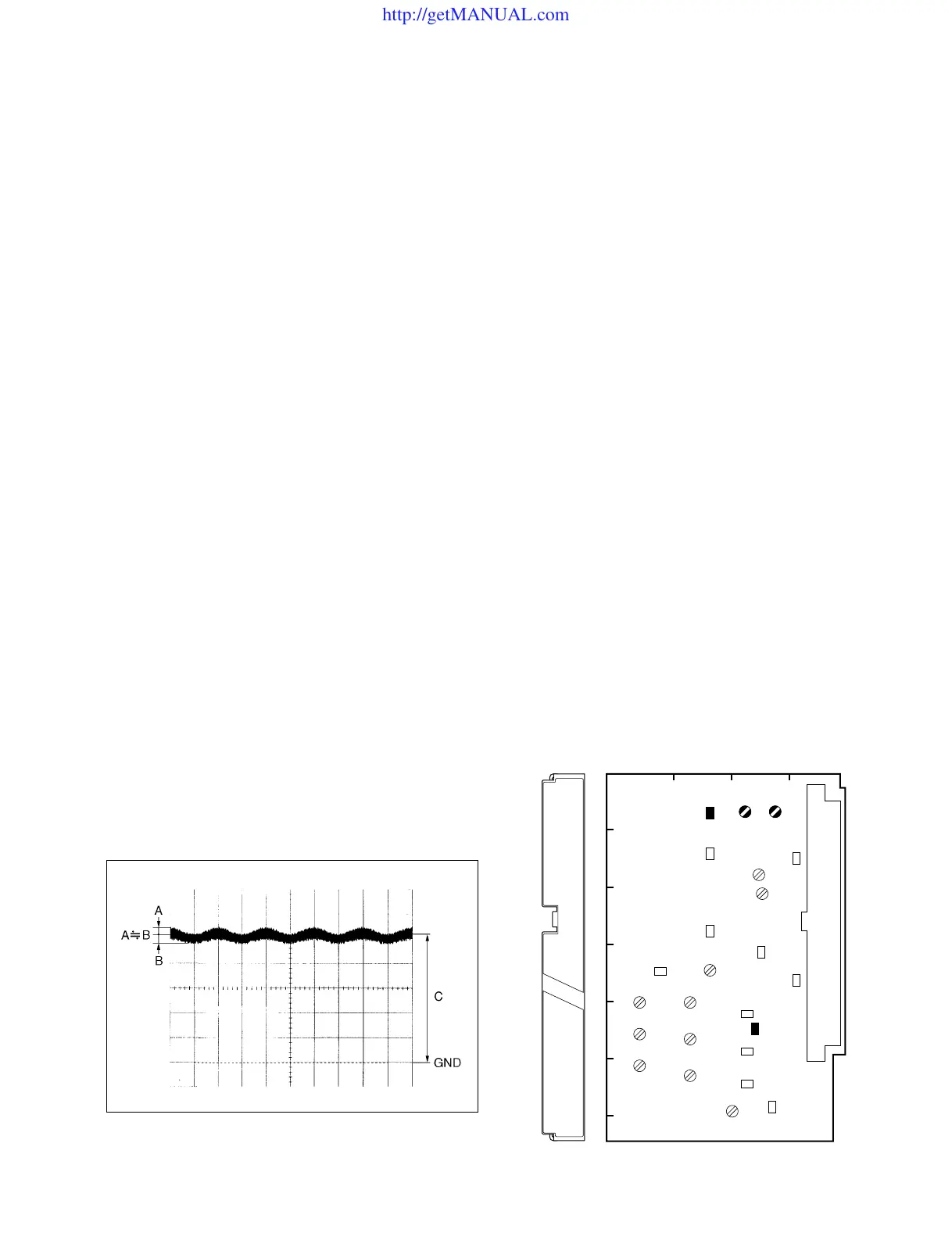
3. Connect the oscilloscope to TP204 (GND:E1)/TR-90
(A-3).
4. Slowly turn 1T202 (A-2) until a sign wave appears
around 5.0 Vdc. Adjust 1T202 for the following
specifications.
Adjustment Point : 1T202/TR-90 (A-2)
Specifications : C = 5.0 ±0.1 Vdc
5. Adjustment Point : 1T203/TR-90 (A-2)
Specifications : The distortion is 0.3% or less
and minimum.
Note :
• After the adjustment is complete, be sure to return S2081
and S2082/AT-88 to their customer-set positions.
TR-90 BOARD (COMPONENT SIDE)
3-3. TR-90 Board Adjustment
A
1
234
B
C
D
E
F
G
TR
T202 T203
TP204
E1
http://getMANUAL.com