3-3 (E)
CA-550
CA-550P
3-1-4. Initial Settings
CA-550/550P
n
When switching the following switches from a customer-
set position, it is recommended to record the setting state
of the customer in the table below.
After adjustment is complete, be sure to return the switches
to their customer-set position.
Board Switch Initial setting Customer-set position
MD-103 S3 GENLOCK
AU-211 SW1 C (CARBON)
SW2-1 OFF
SW2-2 OFF
SW2-3 OFF
SW2-4 OFF
SW2-5 ON
SW2-6 OFF
SW2-7 OFF
SW2-8 OFF
SW3-1 OFF
SW3-2 ON
SW4 OFF
SW5 PHANTOM
SW6 MIC1
DM-98 S1-1 OFF
S1-2 OFF
S1-3 OFF
S1-4 ON
MSU-700 Operation Panel
• CAM POWER/Signal output select buttons
ALL button → OFF (Stays out)
CAM PW button → ON (Stays lit)
TEST 1 button → OFF (Stays out)
TEST 2 button → OFF (Stays out)
BARS button → OFF (Stays out)
CLOSE button → ON (Stays lit)
• CAM/CCU Function ON/OFF buttons
KNEE OFF button → OFF (Stays lit)
DETAIL OFF button → OFF (Stays lit)
MATRIX OFF button → OFF (Stays lit)
AUTO KNEE button → OFF (Stays out)
• Others
GAMMA OFF button → ON (Stays out)
MASTER GAIN button→ 0 (0 dB)
3-2. AU-211 Board Adjustment
1RV1 and 1RV3 on the AU-211 board adjust the VTR
playback audio level and side tone level respectively, and
they can be set according to a customer’s preference.
To output the VTR playback audio or the side tone signal,
switch settings of the AU-211 board are required.
For details, refer to Section 1-4 “Function of Internal
Switches—AU-211 Board”.
3-2-1. BATTERY ALARM SET Adjustment
Note :
• Adjustment for 1RV4 is very critical. Do not turn it as
far as the circuit normally activates.
Equipment : Digital voltmeter Oscilloscope
DC variable power supply
Preparation:
• Supply about +13 Vdc from the DC variable power
supply via the DC IN connector.
Adjustment Point : 1RV4/AU-211 (D-4)
Adjustment Procedures:
1. Turn 1RV4 fully clockwise.
2. Measure voltage at TP84 (GND:GND A)/extension
board (extending AU-211).
3. Adjust the voltage at TP84 for +11.20 ±0.05 V.
4. Slowly turn 1RV4 counterclockwise observing the
waveform at TP42/extension board (extending AU-
211) on the oscilloscope.
5. Adjust 1RV4 so that an 1.0-Hz, 8.0-Vp-p rectangler
wave just appears.
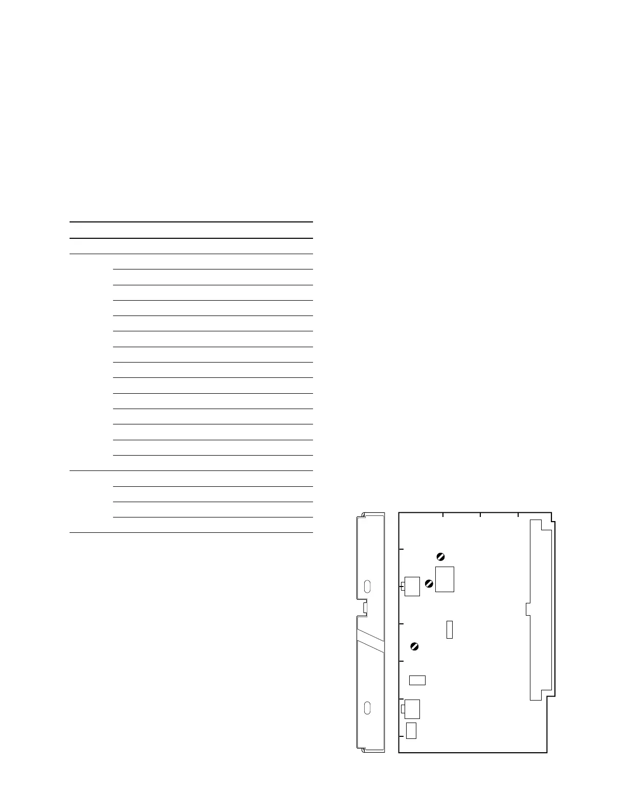
A
1234
B
C
D
E
F
G
AU
MIC PW
ON
OFF
MIC
D
C
RV3
RV1
RV4
AU-211 BOARD (COMPONENT SIDE)
3-1. Preparation
3-2. AU-211 Board Adjustment