3-1 (E)
CA-550
CA-550P
3-1. Preparation
3-1-1. Equipment Required
3-1-2. Notes on Adjustment
• All measuring equipment shall be calibrated.
• Also the alignments for the BVP-550/550P, OHB-450/
451/550/550WS (or their PAL version), CCU-700/700P/
700A/700AP, and MSU-700 shall be completed.
• To connect each equipment, refer to Section 3-1-3.
• As for initial settings before beginning adjustment, refer
to Section 3-1-4.
• Close the camera lens during adjustment.
• Be sure to power off before disconnecting the printed
circuit boards.
• About ten-minute warm-up time is allowed before
beginning adjustment.
• Use a plastic (or ceramic) core driver to adjust 1LV,
1FL, 1T and so on.
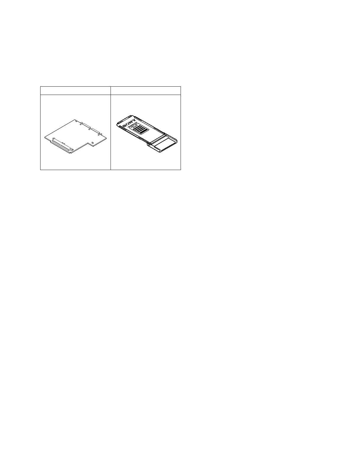
Extension board EX-464 (option)
Sony P/N: J-6395-040-A
For CA-550/550P plug-in boards
Extension board BKP-7900 (option)
For CCU-700/700P plug-in boards
Measuring Equipment
• DC variable power supply
• Frequency counter
Advantest TR5821AK or equivalent
• Spectrum analyzer
• Distortion meter
• Audio generator
• Oscilloscope
Tektronix 2465 or equivalent
• Waveform monitor/Vectorscope
Tektronix 1750 or equivalent (for NTSC)
Tektronix 1751 or equivalent (for PAL)
• Digital voltmeter
Advantest TR6845 or equivalent
• Video signal generator
• Color monitor
Sony BVM-1911/2811 or equivalent (for NTSC)
Sony BVM-2011P/3011P or equivalent (for PAL)
Peripheral Equipment
• Color video camera BVP-550/550P
• CCD unit OHB-450/451/550/550WS series
• Camera control unit CCU-700/700P/700A/700AP
• Master setup unit MSU-700
• AC adaptor AC-550/550CE
• TRIAX cable (Standard length: 150 m)
Section 3
Electrical Alignment