3-5 (E)
CA-550
CA-550P
3-3-4. MIC 2 DEVIATION Adjustment
Equipment : Spectrum analyzer
Audio generator
Preparations :
• CCU-700/700P/700A/700AP setting
S1004 (MIC LEVEL CH2)/AT-88 panel→ NORM
• Feed an 1.0-kHz, -60 dBu (2.2 mVp-p) sine wave signal
from the audio generator to the MIC connector on the
CA-550/550P. (Refer to Section 3-1-3 “Connection —
For audio adjustments”.
Test Point : TP4/TR-90 (F-2)
Adjustment Point : 1RV3 (MIC2 DEV)/TR-90 (F-4)
Specifications : A = 18.0 ±0.8 kHz
3-3-5. INCOM RF Adjustment
Note :
• Use a plastic core driver to adjust 1LV.
Equipment : Frequency counter
Test Point : TP1/TR-90 (E-2)
Adjustment Point : 1LV1 (7.1 MHz)/TR-90 (E-3)
Specifications : 7,100 ±5 kHz
A
1
234
B
C
D
E
F
G
TR
RV3
TP4
TP1
LV1
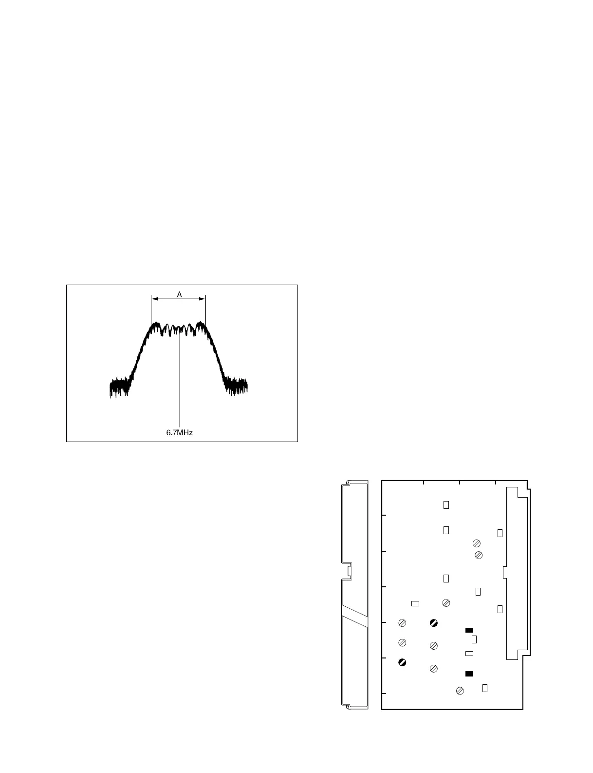
TR-90 BOARD (COMPONENT SIDE)
3-3. TR-90 Board Adjustment
CENTER FREQ 6.7 MHz
SPAN 50 kHz
RBW 1 kHz
Note :
After the adjustment is complete, be sure to return S1004/
AT-88 to its customer-set position.