3-12 (E)
CA-550
CA-550P
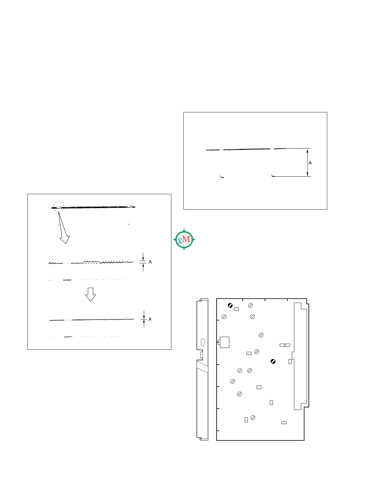
3-4-5. Y/SKIN 90° Adjustment
Notes:
• This adjustment is necessary only when replacing FL2
on the MD-103 board.
• Use a plastic core driver to adjust 1FL.
Equipment : Oscilloscope
Preparation:
• CCU-700/700P/700A/700AP setting
Extend the DM-94 board of the CCU.
Test Point : TP26 (GND:E5)/DM-94 (F-8)
Trigger : SYNC OUTPUT connector/
CCU rear panel
Adjustment Point : 1FL2/MD-103 (C-2)
Specifications : A = 0 ±2 mV
3-4-6. R-Y Level Adjustment
Equipment : Oscilloscope
Test Point : TP63 (GND:TP65)/extension board
(extending MD-103)
Adjustment Point : 1RV5 (VTR R-Y LVL)/
MD-103 (A-4)
Specifications : A = 700 ±14 mV
V rate
H rate
MD
PROMPT
GENLOCK
A
1
234
B
C
D
E
F
G
RV5
FL2
MD-103 BOARD (COMPONENT SIDE)
3-4. MD-103 Board Adjustment