3-14 (E)
CA-550
CA-550P
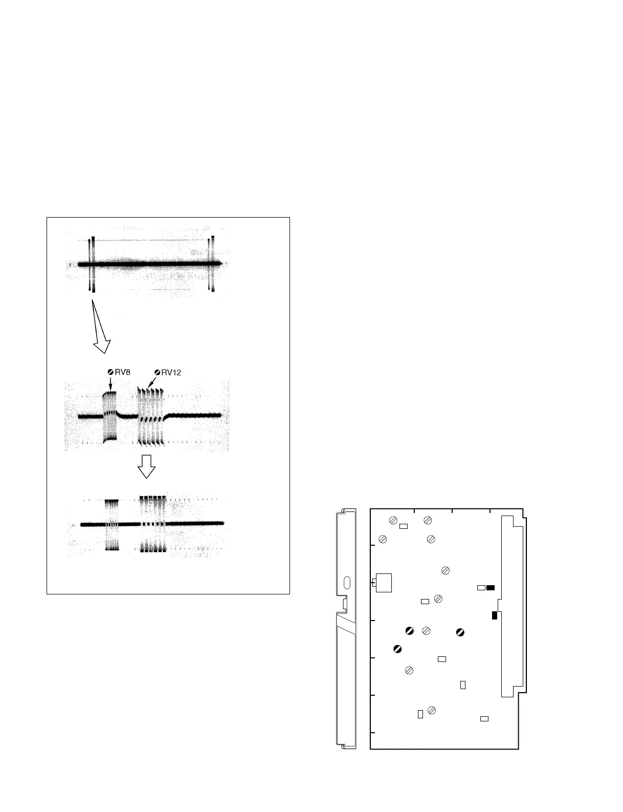
3-4-9. R-Y/B-Y DC Balance Adjustment
Equipment : Oscilloscope (LIMITER→ OFF)
Test Point : TP5 (GND:E1)/MD-103 (C-1)
Adjustment Points :
1RV8 (R-Y DC BAL)/MD-103 (D-4)
1RV12 (B-Y DC BAL)/MD-103 (D-4)
Adjustment Procedure :
Adjust 1RV8 and 1RV12 alternately so that the V BLKG
portions are flat.
3-4-10.R-Y/B-Y 90° Adjustment
Notes:
• This adjustment is necessary only when replacing FL5
on the MD-103 board.
• Use a plastic core driver to adjust 1FL.
Equipment : Digital voltmeter or Oscilloscope
(DC mode)
Preparation:
• CCU-700/700P/700A/700AP setting
Extend the DM-94 board of the CCU.
Test Point : TP14 (GND:E12)/DM-94 (K-5)
Adjustment Point : 1FL5/MD-103 (D-2)
Adjustment Procedure :
Adjust 1FL5 so that a negative absolute value of DC
voltage is maximum.
The voltage changes slowly. When reading the value,
allow for 2 or 3 seconds after turning 1FL5.
V rate
MD-103 BOARD (COMPONENT SIDE)
3-4. MD-103 Board Adjustment
MD
PROMPT
GENLOCK
A
1
234
B
C
D
E
F
G
RV12
TP5
RV8
FL5
E1