3-17 (E)
CA-550
CA-550P
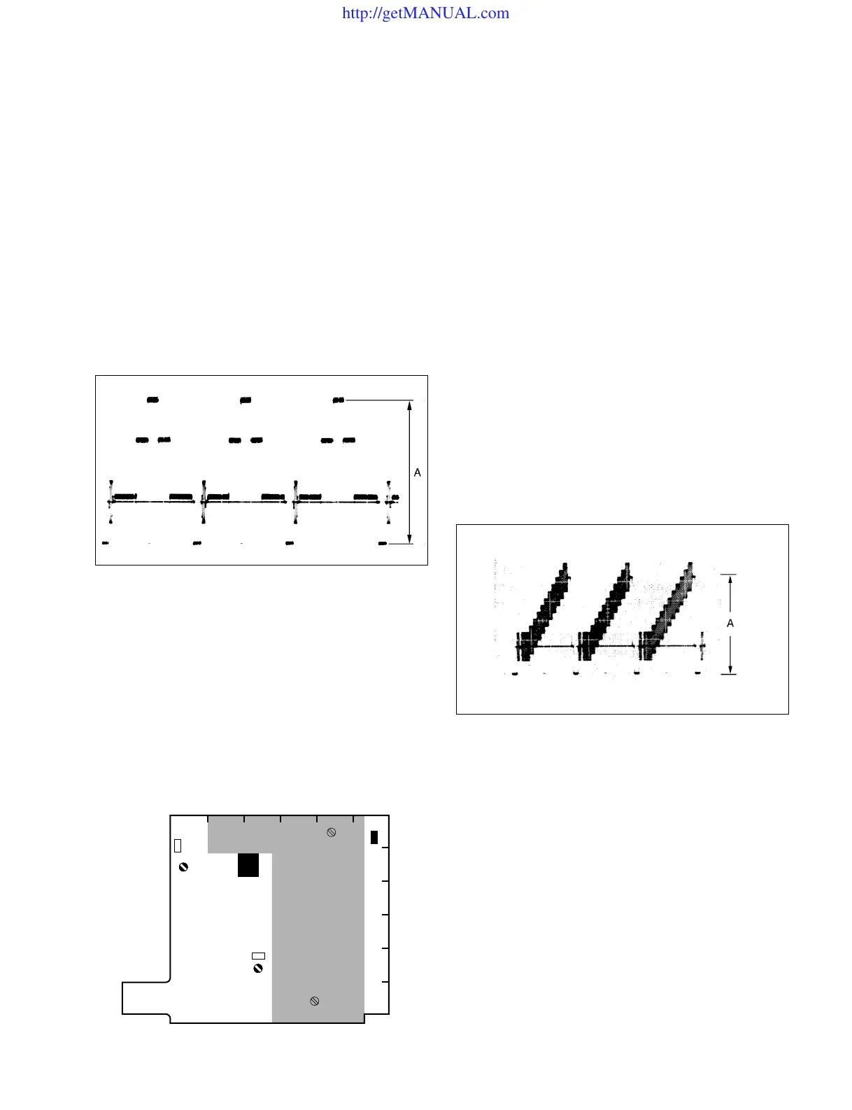
3-5-2. VBS/MONITOR Level Adjustment
Equipment : Waveform monitor
Preparations :
• Set S1-1, S1-3 and S1-4/DM-98 (D-2) to OFF, and set
S1-2 (D-2) to ON.
• Setting of MSU-700 operation panel
TEST 2 button→ ON (Lights)
GAMMA OFF button→ ON (Stays out)
Test Point : RET OUT connector/CA-550/550P
Adjustment Point : 1RV2 (RET OUT)/DM-98 (F-2)
Specifications : A = 1.00 ±0.05 Vp-p
3-5-3. RETURN VIDEO Level Adjustment
Notes:
• This adjustment is necessary only when replacing the
DM-98 board.
• Confirm that the specifications in Step 3-5-2 “VBS
MONITOR Adjustment” are satisfied.
• Use a TRIAX cable whose length is 1000 m or less for
this adjustment.
Equipment : Waveform monitor
Video signal generator
(provides a 10-step signal)
Preparations :
• Set S1-1 to S1-4/DM-98 (D-2) to all OFF.
• Feed the10-step signal from the video signal generator to
the RET 1 IN connector on the CCU rear panel.
Test Point : RET OUT connector/CA-550/550P
Adjustment Point : 1RV1 (RET LEVEL)/DM-98 (D-5)
Specifications : A = 1.00 ±0.05 Vp-p
Notes:
• After the adjustment is complete, confirm that the
specifications in Step 3-5-3 “RETURN VIDEO Level
Adjustment” are satisfied and carry out Step 3-5-3 if
necessary.
• Be sure to set S1-4/DM-98 to ON, and S1-2 to OFF.
• Be sure to turn off the TEST 2 button of MSU-700.
Note :
• After the adjustment is complete, set S1-4/DM-98 to
ON.
A
DM-98 BOARD (COMPONENT SIDE)
3-5. DM-98 Board Adjustment
FEDCBA
6
5
4
3
2
1
S1
RV2
RV1
E1
http://getMANUAL.com