28
DFS-900M Processor Unit
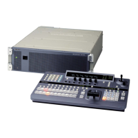
Chapter 2 Names and Functions of Parts
DFS-900M Processor Unit
Front Panel
POWER switch and indicator
Powers the processor unit on and off. Press the = of the
switch to power the unit on. The indicator lights in green
when the unit is powered on.
You can install the optional BKDF-990 Power Supply
Unit for use as a backup power supply. When installed, the
BKDF-990 provides an additional power switch below the
power switch of the standard power supply unit.
For details, see “Installing the BKDF-990 Power Supply
Unit” (page 51).
Rear Panel
1 I/O expansion slots
a I/O expansion slot (upper)
In one slot, you can install two input expansion boards
(third and fourth boards) and one output expansion board
(second board).
POWER switch and indicator
1 I/O expansion slots (see page 28)
2 Standard I/O module (see page 29)
3 External device interface connectors (see page 29)
4 Power connectors (see page 30)
1 I/O expansion slot (upper)
2 I/O expansion slot (lower)