84
Basic Switcher Settings
Chapter 3 Preparations
A settings sub menu of the Input sub menu appears in the display panel.
3
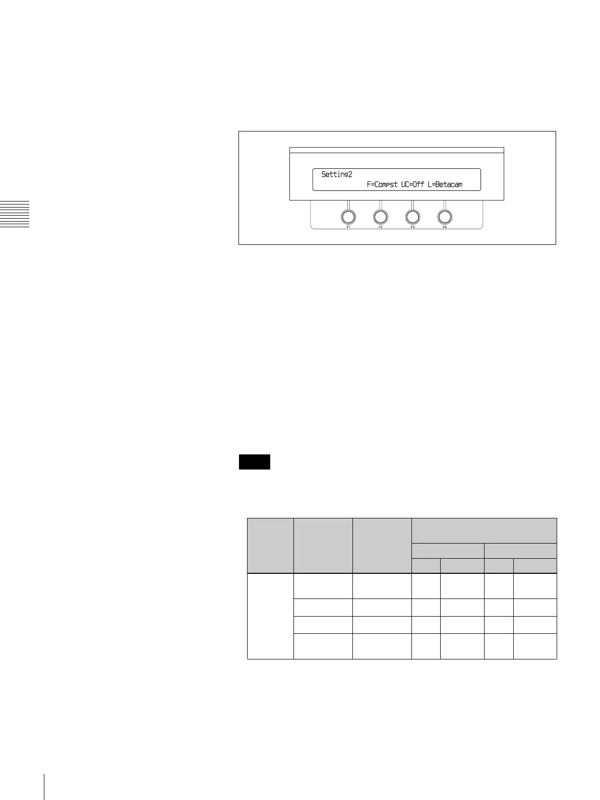
Press the h or H button in the numeric keypad until the Setting 2 sub
menu appears.
“Setting2” appears in the sub menu title display area. If it is already
displayed there, you can skip this step.
4
When using the BKDF-901: Press the PRESET selection button that
selects the analog input you want to set.
If you want to set an analog input that has been assigned by using the
SHIFT button (see page 76), press the SHIFT button before pressing
the PRESET selection button.
When using the BKDF-902: Press the M/E bus B selection button that
selects the analog input that you want to set.
If you want to set an analog input that has been assigned by using the
SHIFT button (see page 76), press the SHIFT button before pressing
the M/E bus B selection button.
5
Rotate the F2 knob to select the type of signal that will be input.
Compst: Analog composite signal
Y/CB/CR: Analog component (color difference) signal
• Analog HD component signals cannot be input.
• The following table shows the input signals and the numbers assigned to
each input channel (see page 39).
Notes
Setting
of step 5
Name of
BKDF-911
connector
Input signal BKDF-911 installation position
and channel number
Lower tray Upper tray
Left Center Left Center
Compst COMP/Y Composite
signal
IN09 IN13 IN17 IN21
R-Y
a)
–––––
B-Y
a)
–––––
COMP Composite
signal
IN10 IN14 IN18 IN22
 Loading...


