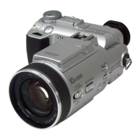
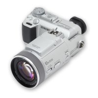
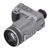
— 2 —
DSC-F828
TABLE OF CONTENTS
6. ADJUSTMENT
1. Before starting adjustment···············································6-1
1-1. Adjusting items when replacing main parts and boards ····6-2
6-1. CAMERA SECTION ADJUSTMENT ···························6-3
1-1. PREPARATIONS BEFORE ADJUSTMENT·················6-3
1-1-1.List of Service Tools ························································6-3
1-1-2.Preparations ·····································································6-4
1-1-3.Discharging of the flashlight power supply·····················6-4
1-1-4.Precaution ········································································6-6
1. Setting the Switch····························································6-6
2. Order of Adjustments ······················································6-6
3. Subjects ···········································································6-6
4. Preparing the Flash Adjustment Box ·······························6-7
1-2. INITIALIZATION OF DATA ·········································6-8
1-2-1. INITIALIZATION OF DATA ·········································6-8
1. Initializing All Pages Data···············································6-8
2. Initializing Single Page Data ···········································6-8
3. 2F Page Adjustment Address···········································6-8
4. 4F Page Adjustment Address···········································6-8
5. 6E Page Adjustment Address ··········································6-9
6. 6F Page Adjustment Address·········································6-10
7. 8E Page Adjustment Address ········································6-11
8. 8F Page Adjustment Address·········································6-11
1-3. VIDEO SYSTEM ADJUSTMENTS·····························6-12
1. Video Output Level Adjustment (SY-096 board) ··········6-12
1-4. CAMERA SYSTEM ADJUSTMENTS ························6-13
1. Data Setting during Camera System Adjustments ········6-13
2. IRIS Reset Sensor Adjustment ······································6-13
3. Flange Back Adjustment ···············································6-14
4. Flange Back Check························································6-14
5. Picture Frame Setting (PTB-450) ··································6-15
6. Picture Frame Setting (PTB-1450) ································6-16
7. Color Shade Check ························································6-17
8. F No. Compensation ······················································6-18
9. Mechanical Shutter Adjustment ····································6-18
10. Light Value Adjustment ·················································6-19
11. Linear Matrix and AWB Adjustment·····························6-20
12. Color Reproduction Check (CAP-Normal mode) ·········6-22
13. Color Reproduction Check (CAP-Real mode) ··············6-23
14. CCD Linearity Check ····················································6-24
15. CCD White Defect Compensation Check ·····················6-26
16. CCD Black Defect Compensation Check ·····················6-27
17. Strobe Adjustment ·························································6-28
18. AF Laser Output Adjustment ········································6-29
19. AF Laser Axis Check ····················································6-30
1-5. COLOR ELECTRONIC VIEWFINDER
ADJUSTMENT·····························································6-31
1. Data Setting during EVF System Adjustments ·············6-31
2. EVF Initial Data Input ···················································6-31
3. VCO Adjustment (SY-096 board) ·································6-32
4. Bright Adjustment (SY-096 board)································6-32
5. Contrast Adjustment (SY-096 board) ····························6-33
6. V COM Adjustment (SY-096 board) ·····························6-33
7. White Balance Adjustment (SY-096 board) ··················6-34
1-6. LCD SYSTEM ADJUSTMENT ···································6-35
1. Data Setting during LCD System Adjustments ·············6-35
2. LCD Initial Data Input ··················································6-35
3. VCO Adjustment (SY-096 board) ·································6-36
4. Contrast Adjustment (SY-096 board) ····························6-36
5. V COM Adjustment (SY-096 board) ·····························6-37
6. White Balance Adjustment (SY-096 board) ··················6-37
6-2. SERVICE MODE ··························································6-38
2-1. APPLICATION FOR ADJUSTMENT (SEUS) ············6-38
2-1-1.Using Method of SEUS ·················································6-38
1. Connection·····································································6-38
2. Operation ·······································································6-38
2-1-2.Precaution on Use of SEUS···········································6-38
2-2. SERVICE MODE ··························································6-39
1. Setting the Test Mode ····················································6-39
2. Bit value discrimination ················································6-39
3. Switch check (1) ····························································6-40
4. Switch check (2) ····························································6-40
5. Switch check (3) ····························································6-40
6. Switch check (4) ····························································6-41
7. Switch check (5) ····························································6-41
8. Switch check (6) ····························································6-41
9. LED, Segment LCD check ············································6-41
10. Record of Use check······················································6-42
11. Self Diagnostics Log check ···········································6-42
* Color reproduction frame is shown on page 6-43.
* AF illumination frame is shown on page 6-44.
 Loading...
