6-30
DSC-F828
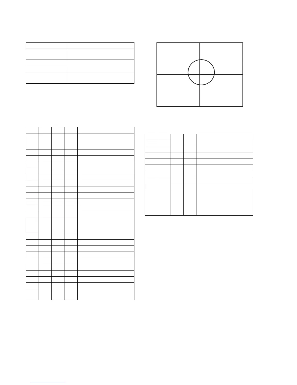
19. AF Laser Axis Check
Check the AF laser optical axis.
Mode STILL(P AUTO) (P)
Subject Background paper (J-2501-130-A)
(1m from the front of the lens)
Measurement Point Monitor TV (under scan)
Measuring Instrument
Specified Value All hologram patterns are within the
inspection frame.
Note1: Perform this adjustment in the dark room.
Preparations:
1) Take a copy of the AF Laser axis frame with a clear sheet.
(Reduce or enlarge the frame in same size as the effective picture
frame of the monitor TV.)
Adjusting method:
Order Page
Address
Data Procedure
1 Check that “1. Data Setting
during Camera System
Adjustments” is performed.
2 60 30 06 Set the data.
3 60 2C 01 Set the data.
4 Set the ZOOM to WIDE end.
5 60 92 05 Set the data.
6 60 93 70 Set the data.
7 60 01 79 Write the data.
8 Wait for 3 sec.
96007
Read the data, and check it is “01”.
10 60 01 00 Write the data.
11 60 22 05 Set the data.
12 60 23 0A Set the data.
13 Check that all hologram patterns
are within the inspection frame.
(Fig. 6-1-15.)
14 Set the ZOOM to TELE end.
15 60 92 05 Set the data.
16 60 93 70 Set the data.
17 60 01 79 Write the data.
18 Wait for 3 sec.
19 60 07
Read the data, and check it is “01”.
20 60 58 01 Set the data.
21 60 14 8A Set the data.
22 60 01 00 Write the data.
23 Check that all hologram patterns
are not unfocused.
Fig. 6-1-28.
Processing after Completing Adjustments:
Order Page
Address
Data Procedure
1 60 14 00 Set the data.
2 60 22 00 Set the data.
3 60 23 00 Set the data.
4 60 2C 00 Set the data.
5 60 30 00 Set the data.
6 60 58 00 Set the data.
7 60 92 00 Set the data.
8 60 93 00 Set the data.
9 If finish the camera system
adjustments, release the data
setting.
(See “1. Data Setting during
Camera System Adjustments”.)
 Loading...