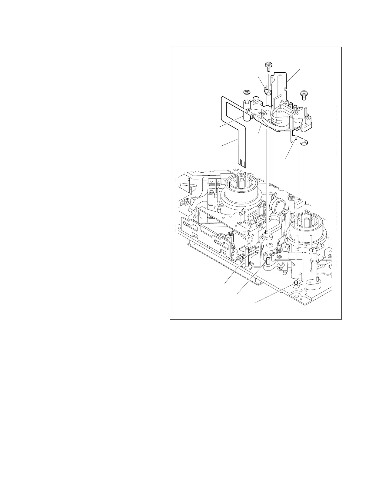
7-55
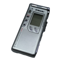
DSR-2000A/2000AP
P1.4 x 3.5
P1.4 x 3.5
Stop washer
MIC assembly
Guide hole
Guide hole
Pin
Pin
Flexible card wire
Boss of MIC arm
Recess
Reel plate shaft
6. Replacing the MIC assembly
(1) Remove the stop washer and the two screws
which secure the MIC assembly to the MD
chassis, and remove the MIC assembly.
(2) Insert a tip of the flexible card wire of a new
MIC assembly between the chassis and the
front MD chassis to bring it to the back side
of the unit.
n
Use great care not to fold and scratch the
flexible card wire during this operation.
(3) Fit the boss of the MIC arm on the shaft of
the MD chassis and also fit the recess on the
reel plate shaft.
Fit the two guide holes in the MIC assembly
on the pins on the MD chassis, and fix the
assembly with the two screws and a new stop
washer.
Tightening Torque : 0.1 N.m {1 kgf.cm}