3-17
DSR-2000A/2000AP
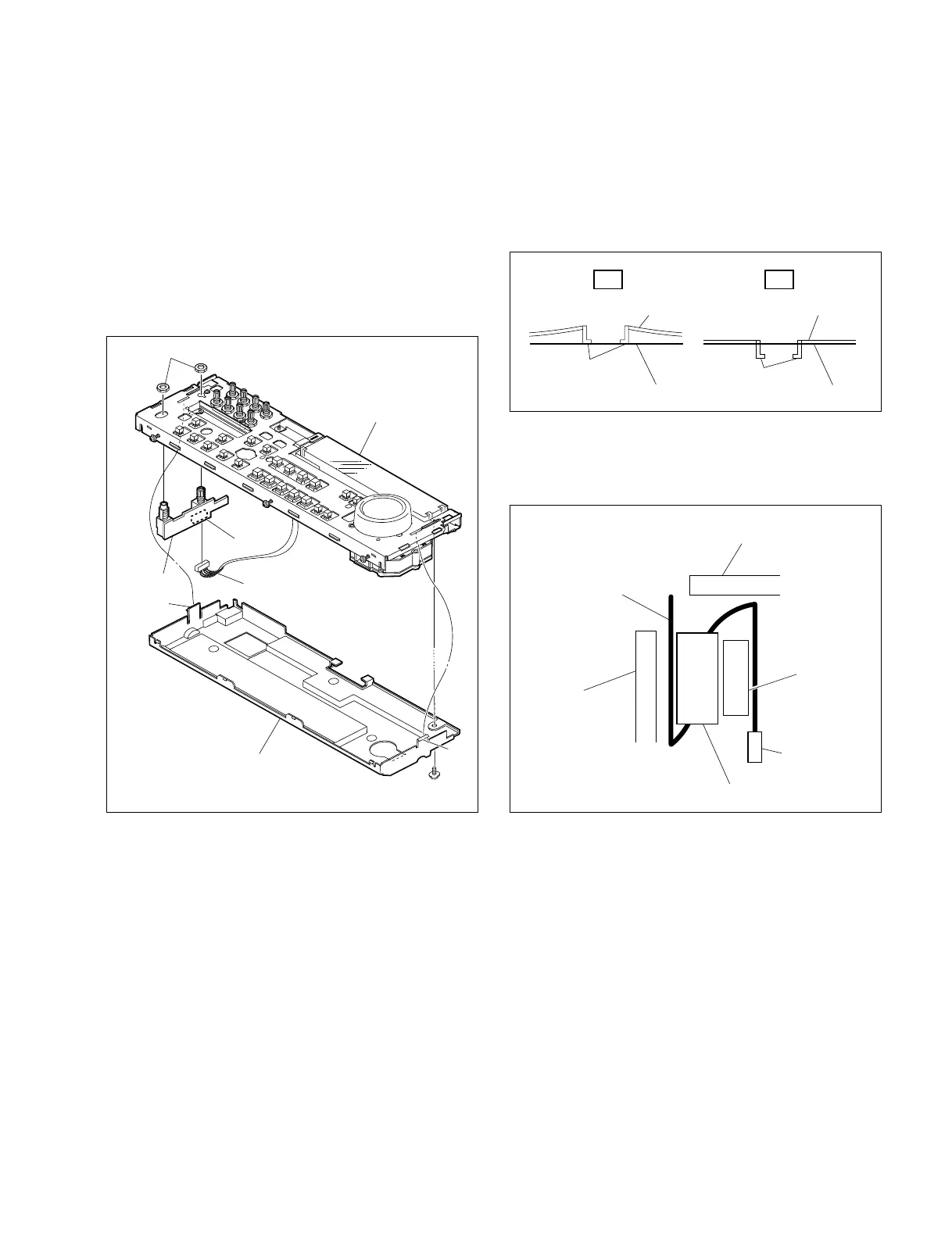
Screw
PWH3 x 6
Claw
KY cover
Harness
Claw
Nuts
Control frame assembly
HP-99 board
CN2
(8) Reattach the HP-99 board in the reverse order of the
removing steps (1) to (7).
m
. When reattaching the KY cover, check that the
portion A is inserted to the control frame assembly
correctly.
. When connecting the flexible card wire to the
connector (CN710) on the KY-452 board, attach the
ferrite core as following figure.
(4) Slide the control frame assembly in the arrow direction
to remove it.
(5) Remove the screw and release the two claws form the
rear side of the assembly and remove the KY cover.
(6) Disconnect the harness from the connector (CN2) of
the HP-99 board.
(7) Remove the two nuts to remove the HP-99 board.
n
Support the HP-99 board from the rear side when
removing the nuts.
NG OK
Portion A
Portion A
Control frame assembly Control frame assembly
KY cover KY cover
CN710
Portion A
Flexible card wire
Ferrite core
Control frame assembly
KY cover