3-18
DSR-2000A/2000AP
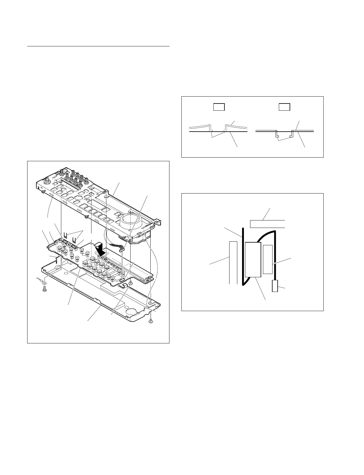
Removal/Reattachment of the KY-452 board
(1) Remove the control frame assembly. Refer to this
section Removal/Reattachment of the HP-99 board,
steps (1) to (4).
(2) Remove the screw (PWH3 x 6) from the rear side and
remove the KY cover.
(3) Disconnect the two flexible card wires from the
connectors (CN714 and CN713) of the KY-452 board
and also the harness from the connector (CN711) of
the KY-452 board with tweezers.
(5) Remove the four screws securing the KY-452 board.
(6) Disconnect the harness from the connector (CN712)
while lifting the KY-452 board.
(7) Reattach the KY-452 board in the reverse order of the
removing steps (1) to (6).
m
. When reattaching the KY cover, check that the
portion A is inserted to the control frame assembly
correctly.
. When connecting the flexible card wire to the
connector (CN710) on the KY-452 board, attach the
ferrite core as following figure.
NG OK
Portion A
Portion A
Control frame assembly Control frame assembly
KY cover KY cover
CN710
Portion A
Flexible card wire
Ferrite core
Control frame assembly
KY cover
Screw
PS3 x 6
CN711
CN714
CN713
CN712
Screw
PWH3 x 6
Screws
PWH3 x 6
Claw
KY cover
Flexible
card wires
KY-452 board
Harness
Claw
Control frame